July 7, 2012 (7/7/12) - This page contains notes about embedded
processors, aka microcontrollers - tiny computers that give smarts
to a wide range of devices, including PC keyboards, toasters,
toys, GPS units, TV sets... they're all around. They come in sizes
ranging from 3mm 6-pin packages to relatively fast processors
running a full-blown operating system. There's no fine dividing
line between embedded processors and general-purpose computers but
usually (but not always) embedded processors have ram, rom and
nonvolatile eeprom built into the same chip and require very few
external components for the computing portion. Modern cell phones
and tablet computers often use high-end embedded processors (ARM
etc) but blur the line between fixed devices and general-purpose
computers. The Embedded
system Wikipedia page covers the subject well. The kinds of
apps I've used embedded processors for are comparatively simple,
including making sounds or playing melodies, monitoring battery
voltage, automatic power-off, monitoring momentary switches to
produce latched outputs, various kinds of testers and hobby/fun
stuff - these sorts of apps basically just monitor digital and
analog input pins and set digital output pins according to an
internal fixed algorithm stored in rom. If more than that is
needed (for example an operating system with file capabilities)
then it makes more sense to use one of the many available
single-board computers, but almost everything I need to do can be
done with a cheap PIC or similar processor, requiring little more
than a bypass capacitor between the supply pins plus whatever
circuitry I need to control.
Other pages around here with hobby-oriented embedded processor
information include...
A-Life, Robotics and Other
Worlds - links to small PIC-based robots (old... I don't
maintain that page any more)
HP Minicomputer Projects - includes
an IDE disk interface for a HP21xx minicomputer using an
8052-based "Paul" board
USB Disk Adapter - a USB disk
interface for a HP21xx minicomputer using a PIC18F2525, an LCD,
and a VDRIVE2 module
Skip ahead on this page...
3-wire LCD code and hardware - an
easy/reliable way to connect a 16x2 LCD to a PIC18F2525
Open Source Compiler Licenses - know what
you can and can't do with the output of a compiler
Using MPLAB-X (and SDCC) - using the
new Microchip IDE and making it work with SDCC
Use What Works - opinions are
relative depending on what needs to be done
Getting Stuff Done - finding the right mix
between modern and simple
SIMPLE2 - a (sort of) modern version of my
old dos SIMPLE compiler for PIC12/PIC16 chips
An old PIC interpreter - some old
robotics code that interprets a HLL program from eeprom
gcboot_small - a PIC18F2525 bootloader
written in Great Cow Basic
Developing
Embedded Applications Under Linux
7/1/12 - My main gig these days is designing electronic circuits.
Usually it's mostly analog stuff using transistors, opamps, etc
but sometimes I need "smarts", for this I turn to tiny processors
aka microcontrollers. The ones I typically use come in packages
ranging from 8 pins to 28 pins, run from about 4mhz to 32mhz, have
from a few dozen to a few KB of RAM, about 2KB to 48KB of ROM for
program code, and if needed about 256 bytes to 1KB of non-volatile
eeprom storage. Usually the only external components are a
decoupling capacitor, sometimes a reset circuit, and whatever it
is I need to control. Typical applications include converting
push-button switches to patterns of on/off lines, power supply
control including stuff like blinking an LED if the power is low
and/or automatic power off, various kinds of test equipment, and
anything that needs internal computing or logic for very low cost
- usually from about $1 to $5 or so. My favorite microcontroller
chips are the 8-pin PIC12F629 and PIC12F675 for cheap simple
logic, the 14-pin PIC16F684 when I need a few more lines, and the
28-pin PIC18F2525 for more intense apps.
For the PIC12 and PIC16 parts I use a Microchip Pickit 1
programmer, using the free usb_pickit software. There are several
varients of this software, I'm using a version put together by
David Henry, dated 2006/8/20, later versions are
available. To make it easier to use I made a few scripts...
----- pickit-burn -----
#!/bin/bash
# burn a PIC using usb_pickit
usb_pickit --program="$1"
echo ---Press Enter---
read nothing

----- pickit-extract -----
#!/bin/bash
# extract hex from PIC using usb-pickit
echo "Will extract PIC and overwrite $1"
echo "Press Enter to proceed or close window now..."
read nothing
usb_pickit --extract="$1"

----- Pickit_Burn -----
#!/bin/bash
gnome-terminal -x pickit-burn "$1"

----- Pickit_Extract -----
#!/bin/bash
gnome-terminal -x pickit-extract "$1"
...the Pickit_Burn and Pickit_Extract scripts are for associating
to *.hex files to use via the GUI. For easy access to the USB port
without having to be root or otherwise jump through hoops I made
the usb_pickit binary setuid-root - sudo chmod a+s usb_pickit.
There may be other ways to do this such as adding yourself to the
appropriate group (which varies, maybe dialout).
To convert assemble code into hex files for burning I typically
use the Tech-Tools cvasm16 assembler (I prefer the Parallax
syntax), version 6.2 from 2002, later versions
available here. It's wrapped in a Windows installer but the
assembler is a plain dos application and works under
DosEmu/FreeDos.. wine can be used to run the installer then copy
the files into the dos environment. Setting up the dos environment
is beyond the scope of this description (it helps to have been
around computers in the '80's and '90's), but once installed I run
it from Linux using the following script (dosroot= must be edited
to where the dos files are)...
----- cvasm16 -----
#!/bin/bash
dosroot=~/MYDOS
if [ -e "$1" ]; then {
 bn=`basename "$1"`
 pn=`dirname "$1"`
 if [ -n $bn ]; then {
  mkdir $dosroot/cvasm.tmp
  cp -f "$1" $dosroot/cvasm.tmp
  unix2dos $dosroot/cvasm.tmp/$bn
  xdosemu "cvasm16t.bat $bn"
  cp -f $dosroot/cvasm.tmp/*.lst "$pn"
  cp -f $dosroot/cvasm.tmp/*.hex "$pn"
  rm $dosroot/cvasm.tmp/*
  rmdir $dosroot/cvasm.tmp
 } fi
} fi
...which runs a dos batch named cvasm16t.bat which contains...
@echo off
cd cvasm.tmp
d:\dos\pictools\cvasm16.exe /L /M %1
pause
Once cvasm16 does its thing and dosemu exits, the script copies
the resulting .hex and .lst files back to whatever directory the
source .asm file was in when running the assembler - semi-complex
stuff needed to make it all work but the end result is I can
right-click an assembly file and assemble it, then right-click the
hex file and send it to the Pickit programmer to burn the code
into a chip. Pretty much the same way I've been doing it for the
last 15 years or so (before that had to use the dos prompt),
before the Pickit I used a homemade programmer that interfaced via
a parallel port - good luck finding one of those these days, the
USB-based Pickit is definitely a step up. There are Linux-based
PIC assemblers including gpasm from the gputils package, but I'm
not crazy about the stock Microchip assembler language, the
Parallax syntax suits me better. Of course if learning this stuff
from scratch, probably doesn't matter but for me just because I
moved to Linux doesn't mean I want to give up the software I'm
used to.. I just emulate it.
Simple apps don't need much from the software... reading and
setting pins and adding and subtracting byte numbers, but still
assembly can get tedious so long ago I wrote a compiler called
"SIMPLE" in QBasic (zip here),
all it really did was translate more normal syntax like a = b + c
and if bit then do something else do something else endif into
equivalent cvasm16 instructions but that was enough. Once again it
came from the days long before I was running Linux and I kept
using it under DosEmu/FreeDos. Here's the script I run it with...
----- PICsimple -----
#!/bin/bash
# compiles a PIC program written in "simple"...
# uses unix2dos on the source file to make sure crlf returns
# copies file to [dosroot]/simple.tmp/[filename]
# runs "sim2hex.bat" using DosEmu
# copies .src .lst .hex files back to where they came from
# contents of sim2hex.bat...
#
# :: compile a pic program using SIMPLE then assemble using CVASM16
# :: don't specify path.. either change to dir first, or put in \simple.tmp
# :: creates .SRC .LST and .HEX files with same basename
# @echo off
# cls
# echo.
# if exist \simple.tmp\%1 cd \simple.tmp
# if not exist %1 goto end
# md compile.tmp
# copy %1 compile.tmp\*. > nul
# cd compile.tmp
# for %%f in (*.) do set basename=%%f
# cd ..
# del compile.tmp\*.
# rd compile.tmp
# echo Compiling %1 using SIMPLE...
# call simple %1
# if not exist %basename%.src goto error
# echo Assembling %basename%.src using CVASM16...
# call cvasm16 /L /M %basename%.src
# if exist %basename%.hex goto end
# :error
# echo.
# echo ***** ERROR *****
# if exist %basename%.src goto error2
# echo Compiler error, .src .lst .hex files not updated
# goto error4
# :error2
# if exist %basename%.lst goto error3
# echo Assembly error (see .lst), .hex file not updated
# goto error4
# :error3
# echo CVASM16 error, .lst and hex files not updated
# :error4
# pause
# :end
#
dosroot=~/MYDOS
if [ -e "$1" ]; then {
 bn=`basename "$1"`
 pn=`dirname "$1"`
 if [ -n $bn ]; then {
  unix2dos "$1"
  mkdir $dosroot/simple.tmp
  cp -f "$1" $dosroot/simple.tmp
  xdosemu "sim2hex.bat $bn"
  cp -f $dosroot/simple.tmp/*.src "$pn"
  cp -f $dosroot/simple.tmp/*.lst "$pn"
  cp -f $dosroot/simple.tmp/*.hex "$pn"
  rm $dosroot/simple.tmp/*
  rmdir $dosroot/simple.tmp
 } fi
} fi
The batch it requires on the dos side is listed in the script
comments. Of course I have .sim files associated to the PICsimple
script so I can code, right-click, compile, then I can burn the
resulting hex file into the chip... I don't mind complexity when
setting things up but when I'm coding an app I want it to be as
easy as it can possibly be. So far, except for usb_pickit, I'm
just reusing the same dos programming tools and techniques I've
used since the Win95 days, just running it under Linux, and for
simple PIC12 and PIC16 apps it's enough to get the job done.
But sometimes I need more. For some apps 8051-based systems are
appropriate, such as the "Paul" board I used for an IDE interface
for my HP2113 minicomputer, but
that approach is too many chips and too much power for most of the
apps I need an embedded processor for, so for my USB disk interface for the same
antique computer I chose the PIC18F2525 processor with 48KB flash
rom, almost 4KB ram and 1KB eeprom, running at a whopping 32mhz
(with no crystal, the internal clock is within 1%, close enough
for serial). This is a really nice part, burn code into it using a
Pickit 2 programmer, hook up power and it's good to go, not sure
how much power it draws but under 40ma going full speed and under
10ma when running at a more modest 8mhz. Microchip supplies a
Linux version of the Pickit 2 burning software (pk2cmd), setuid to
root to avoid hassles accessing the USB port. Here are a couple
scripts I use with pk2cmd...
----- burn18 -----
#!/bin/bash
# erase PIC (preserve EE) and burn hex file
pk2cmd -T -R -P -M -Z -F "$1"

----- pk2on ------
#!/bin/bash
# turn on the pickit 2 and run app
pk2cmd -P -T -R
For some unknown reason, burn18 won't work from my Ubuntu GUI,
even when wrapped in a terminal launcher - says "hex file not
found" even though the parms are correct... so have to use these
from a command line.
Update 12/28/12 - seems the problem is the hex file has to be in
the current directory, the following script can be associated to
.hex files...
----- PicKit2_Burn -----
#!/bin/bash
# erase PIC and burn hex file from a GUI
if [ "$2" == "doit" ];then
 echo "Burning $1"
 cd `dirname "$1"`
 fname=`basename "$1"`
 pk2cmd -T -R -P -M -K -F "$fname"
 echo "--- press a key ---"
 read -n 1 nothing
else
 if [ -f "$1" ];then
  xterm -e "$0" "$1" doit
 fi
fi
I wrote the USB disk adapter code in a language called Great Cow Basic,
which is written in FreeBasic and compiles for Linux just fine.
The app I was writting was kind of intense, with the help of the
author I fixed a couple of bugs to let it use rom past 32KW and
other things, the latest version includes some of the fixes, the
version I use is archived here. GCB
has some quirks, in particular have to be careful when converting
between bytes and integers, but it gets the job done. One cool app
I made with it was a bootloader
that once programmed into the chip permits loading unmodified hex
program files into the chip using a 9600 baud serial connection
(ground, tx, rx), avoiding having to pull the chip from the app
circuit to use a programmer. Also includes a simple user interface
for examining ram and rom and clearing memory, useful for seeing
what changed after running the app code. Almost any serial
terminal emulator can be used, however when uploading hex code
there needs to be some delay after each line to give the
bootloader time to write the code to flash, so I associate hex
files to another script...
----- sendhex -----
#!/bin/bash
if [ -e "$1" ]; then
 serial=/dev/ttyS0
 stty -F $serial 9600 cs8
 filename="$1"
 while read line
 do
  echo $line > $serial
  sleep 0.05
 done < "$filename"
 sleep 0.1
 echo "" > $serial
 sleep 1
 echo -n "x" > $serial
fi
...the script sends a return then an "x" to execute the code
after uploading since that's usually what I want to do, the serial
terminal can remain connected to monitor for errors and interact
with the app (if serial-enabled) after running. Cool stuff. But as
usual with cool stuff there is a downside - LGPL. I'm fine with
the LGPL for PC apps, and I think authors should be credited for
their work. But it doesn't work for embedded because to use GCB
(or any other compiler that includes LGPL libraries) I have to
supply the copyright notice and make it possible for the user to
relink to another version of the libraries. For a PC amp that
means nothing if the libraries are a dependency, and if included
just means a copyright file has to be included. However, GCB
intermixes library code with application code (and there's no easy
way to not use library code), so the actual source code for the
application has to be supplied to comply with the licensing
requirements. OK for open source, generally not suitable for
commercial purposes.
Recently I had a request for a new product prototype.. this one
requires floating point math and displaying information on an LCD
screen, and I needed a mockup fast. So I grabbed an Arduino and
connected it to a serial Parallax LCD (both bought at Radio
Shack). I'm not crazy about Java but the Arduino programming
software worked fine under Linux. The Arduino Uno uses an
ATMEGA328 processor, similar in capabilities to the PIC18F2525. It
certainly made programming easy, despite being C it only took a
couple of days to write the mockup demo software and the client
was impressed. At first I thought maybe it could be possibly
useful for commercial work.. separate objects are created so it's
possible to relink them without revealing the app source, but once
I got to the nitty gritties it's still not practical, to comply
I'd have to add a dozen or so pages of license text to the manual.
Problem is, there is no manual, and it's not my product. I'm just
designing a gizmo and have no control over what the client does
once it's purchased, and I certainly can't justify all that extra
printing of legal mumbo jumbo for a chip that just reads some
inputs, sets some bits, does some math then writes stuff to an
LCD. I'm all for giving credit but it should be as simple as
putting a sticker on the chip, writing on the PCB or a line in a
manual saying something like "Powered by Arduino and lib-avrc".
The real problem is any restrictions at all on the code produced
by a compiler when compiling only user code with no addons is a
bigtime issue. Sure copyright the compiler app itself but
copyrighting the output code as well pretty much makes it useless
for any kind of commercial usage. If that's the intent then fine,
but if the intention is for the code to be widely used, then lose
the restrictions.
So back to reality... and the Microchip web site. The Microchip
tools have progressed quite a bit since I last tuned in, now they
have Linux versions of MPLAB, Hi-Tech C18 and Microchip's own C
compiler for the PIC18 series, they do floating point, and are
totally free to use for any purpose. They aren't open source but
at least they output the assembly so I can verify/fix things
should I run into a compiler bug. Hi-Tech C seems a bit simpler so
going with that for now, took a few days to get familiar with the
syntax but I think I'm getting the hang of it, managed to write my
own hardware serial and analog input drivers, didn't take that
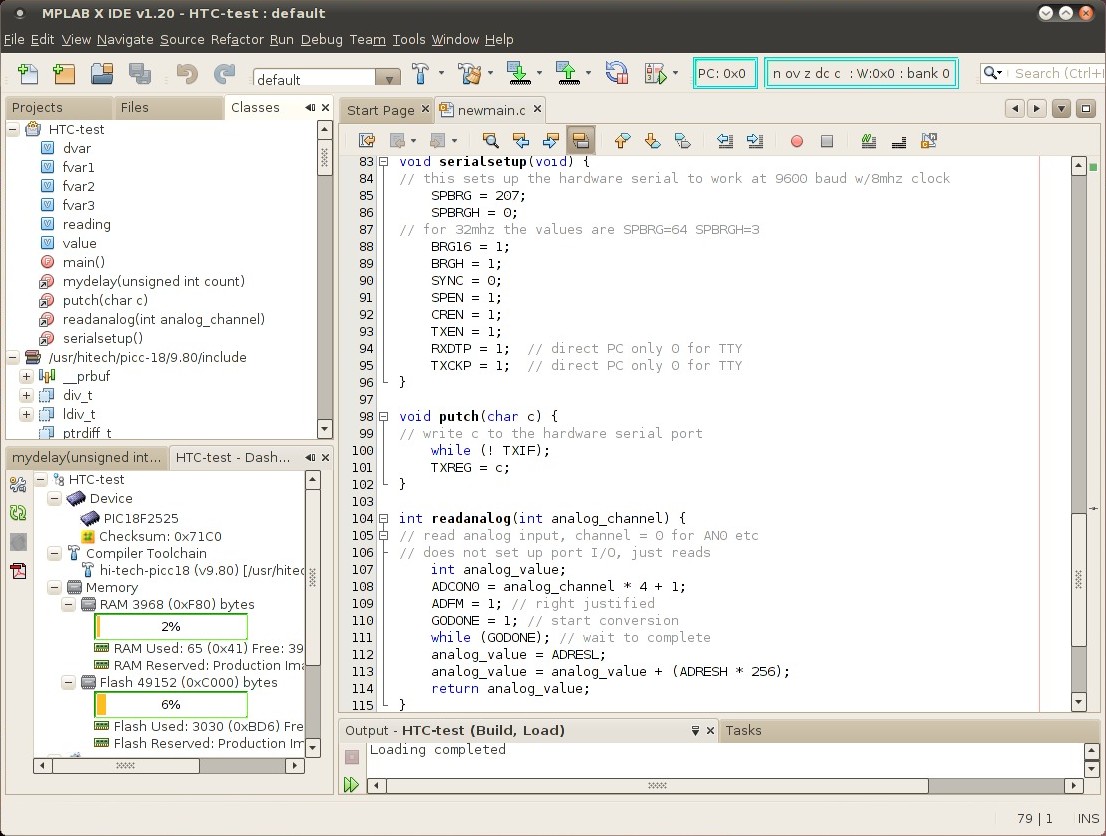
much effort. Actually it's pretty cool stuff...
The code window shows my simple serial output and analog input
functions... not much to it.
The Hi-Tech picc18 compiler can also be used from the command
line, here's the script I use...
----- compile18 -----
#!/bin/bash
/usr/hitech/picc-18/9.80/bin/picc18 --chip=18F2525 \
--rom=0-AFFF --double=32 --float=32 --asmlist $*
This one can run from a GUI gnome-terminal etc wrapper like other
examples, but need add a cd `dirname "$1"` to the beginning (after
the #!/bin/bash) to change to the directory where the files are,
and add a sleep 3 to the end so compiler messages can be seen. The
hex files produced by Hi-Tech C can be loaded using my gcboot
bootloader provided the --rom line cuts off the code before the
bootloader starts (for the PIC18F2525 it's B000 so top of rom is
AFFF), code is generated from the top of rom down.
I haven't really tried the Microchip C18 compiler, it's installed
but so far haven't had any luck using it from a command line.
7/3/12 - The new XC8 compiler is suppose to replace both the
Hi-Tech and Microchip C18 compilers. I tried it and immediately
ran into a very strange issue - setting port B bit 4 makes the
processor reset, but not immediately, takes a few dozen
milliseconds during which time the code continues to run. This is
an interrupt-on-change pin but interrupts are supposed to be off
(INTCON=0) and setting port B bit 5 does not cause the reset. XC8
compiles to less code and printf supports 32 bit floats (Hi-Tech's
printf uses 24 bit precision regardless of the float setting), but
this is just too weird. There are other issues with XC8 under
MPLAB X - at first could not get to the linker options but the
options magically appeared after "doing stuff" (manage
configurations, accessing other options etc), and whenever going
to the configuration options, upon return all the chip variables
get flagged as unknown until I edit/restore the library #include
line to make it rescan... irritating. XC8 almost works, there
might be an setup option that fixes RB4, but presently it's too
buggy here to use.. continuing with Hi-Tech PICC18 which has none
of these issues.
Funny... the more capable (and it appears, the more expensive) the tools are, the more likely they will fail. CVASM16 and my SIMPLE compiler has no bugs that I know of - the compiler is mostly just a string substitution program and only supports a few dozen commands so bugs would be obvious. Primitive as it may be, it's still my primary tool for programming PIC12 and PIC16 parts - does what I want it to do and I don't want it to do anything else. I ran into a few bugs with Great Cow Basic... but the program is only a few hundred K of FreeBasic code, not that hard to track down and fix problems. I ran into no bugs using the Arduino stuff. I get the feeling this commercial compiler stuff is going to be a bumpy ride.
7/7/12 - I downloaded a couple open-source PIC18 compilers to
check out.. cpik version
0.7.1, and SDCC
version 3.2.0 (2012-7-7 daily source).
The cpik compiler compiled without problems (using qmake),
however I'm having trouble with printf - the link phase produces
undefined symbols "C18_printf" and "C18_set_putchar_vector"
[update 7/9/12] - the trick is to add stdio.slb [or
stdio-small.slb] to the link command line. This is an interesting
compiler - it's simple, has a flexible library system that uses
assembly source modules (rather than binaries), the assembly
output file is complete, and it has implicit bit references
(somevar.bit) without having to use structs. But it is different,
existing HTC/SDCC-style source needs modifications [update
7/10/12] - was somewhat tricky but got the LCD test program
working, see below.
The SDCC compiler includes support for numerous processors. The
daily source package compiled (installed bison, flex and
stx-btree-dev to make configure happy), apparently it did not
successfully compile all of the libraries so replaced lib/pic16
with the directory from the binary version of the package
downloaded at the same time. Same with non-free/lib/pic16. It's a
daily, probably got the wrong version, didn't exactly read the
docs, just poked it until it went then cleaned up afterwards...
still it didn't take that much effort to get it working (probably
a lot less effort just installing a recent binary package but one
of the goals was to make sure I can recompile it if necessary). I
did have to read the docs and do lots of googling to figure out
how to make it compile code, but managed to get it to work -
modified the LCD test program I got running under Hi-Tech PICC18,
once I figured out the config bit and pin names and how to
configure stdout it worked fine. By default (unless the libraries
are recompiled) the printf function does not support floating
point prints, but floating point prints are rarely needed and it
only took a couple of minutes to figure out how to fake a x.x
display using integer prints.
For me, the best feature about SDCC (besides that it appears to
work) is since version 3 (November 2010) most of the library code
has been re-licensed to GPL + LE, so it's fairly easy to make sure
that restricted code is kept out of the output stream. This is in
my opinion the solution to licensing open-source compilers for
embedded processors, it provides strong protection for the
compiler and the library source code while not preventing embedded
programmers from using the compiler to make a living. Also, people
are more likely to identify and if possible fix bugs or otherwise
contribute when it's something that can be used for "real"
applications as opposed to being limited to personal or hobby use.
3-Wire
LCD code in C for the PIC18F2525
This is a simple "get it going" application that connects a
28-pin PIC18F2525 processor to a common 16x2 LCD display with a
6-pin programming port for loading the code using a Pickit 2
programmer. The hardware is wired as follows...
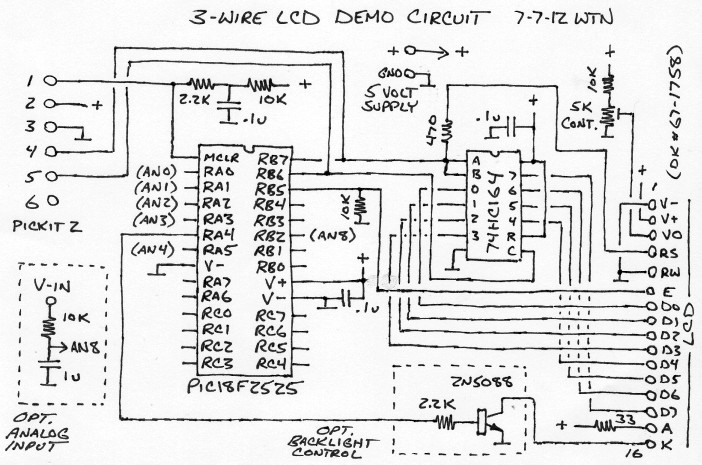
The schematic should be self-explanitory, if not then do some
studying.. basic electronics and PIC knowledge is assumed. This
circuit and code should work with most 2-line LCD's that use the
common Hitachi 44780 controller but be sure to check the LCD
pinout. Especially the V+ and V- lines, getting those wrong would
be not good (poof). The circuit was inspired by the connections on
this
page and on this
page.
There are oodles of 2 and 3 wire LCD interfaces but I really like
this one... it uses essentially a single dirt-common 14-pin shift
register and because it operates in plain byte mode the software
is a lot simpler (and when trying to figure out how to make
unfamiliar compilers work I definitely want simple). The data line
feeds both the shift register input and the LCD's RS line (which
determines whether a byte is a command or data), the clock line is
used to load the data into the shift register using very simple
code then once the data is loaded the data line is set to indicate
command or data then the enable line is pulsed. It doesn't get
much simpler than that. To minimize pin impact the clock and data
lines share the in-circuit programming pins (RB6 and RB7), RB5 is
the enable line to group with the other pins and avoid triggering
LCD commands when programming. The 470 ohm resistor in series with
the RS line isolates the LCD and wiring from the circuit to avoid
possible issues when programming, and the 10K resistor on RB5
pulls the enable line low when the pins are tri-stated. The
circuits in the dashed boxes are used by the demo code for
controlling the LCD backlight and measuring an analog voltage
input, totally optional, eliminate the transistor stuff and ground
the K line to power the LCD backlight all the time.
Here is the test code... (txt extension added for web display,
crlf line ends)
(updated 9/7/15 to fix dumb bug, avoid warnings and work with
latest SDCC - not retested but should work)
picc18_lcd_test.c - for the
Hi-Tech PICC18 compiler (v9.80), tested using the MPLAB-X IDE
sdcc_lcd_test.c - for the SDCC
compiler (v3.2.0 2012-7-7 daily), tested using command line and
pk2cmd
cpik_lcd_test.c - for the cpik
compiler (v0.7.1), tested using command lines and pk2cmd
The Hi-Tech and SDCC versions are very similar, the main
differences are the config lines, the include lines, how port bits
are specified in the defines, and how the stdout character driver
is configured. To make printf work the Hi-Tech PICC18 compiler
requires the user code include a putch(char) function, doesn't
seem picky about whether it's signed or unsigned so went with
unsigned to simplify the code. The user code needs a function
declaration for the putch function. SDCC requires a user-supplied
putchar (char arg) __wparam function and it has to be in that
form, can be declared or not but if declared must match the
existing library declaration, and stdout = STREAM_USER must be run
before doing prints. Because it wants a normal (signed) char extra
code is added to putchar to convert to unsigned so that the
comparisons will work.
The cpik version (added 7/10/12) needed extra modifications - all
int types (16 bit) were changed to long, L was added after all
constants relating to 16-bit calculations and U was added after
byte comparison constants >=128 to avoid signed/unsigned
comparison errors. The LCD byte driver is in the
writeLCDbyte(unsigned char) function, with the myputch(char)
function chaining to it, set_putchar_vector(&myputch) hooks up
standard output to myputch. 16-bit number prints need the format
string "%ld". The bit names in the config lines were determined by
looking at gpasm's 18f2525 header file. Some of these things could
probably be done more efficiently.
The LCD "driver" code includes an initLCD function that has to be
run before using, afterwards printf can be used to print strings
and numbers (once connected to the LCD byte driver) and
putch/putchar/writeLCDbyte (named differently in the different
versions) can be used to send single characters or control bytes.
The control scheme is a subset of the Parallax(TM) serial LCD
commands for turning the display on and off, configuring cursor
and blink and positioning the cursor, see the comments. Besides
setting up putch/putchar functions in a way to make the compiler
happy, the code requires that LCDenable, LCDclock and LCDdata be
defined to the appropriate bitfields corresponding to bits/pins in
LATB (the port B latch.. directly addressing port B pins doesn't
work in C since it has to read the current values to change bits,
LATB contains the current state and changing a bit changes the
corresponding pin state). The mscalibrate define needs to be set
to how many loops it takes for while(count--) to delay by about
1ms, for an 8mhz clock something around 300 should be in the right
range (the constants in the code are approximate).
The pins are configured so that RA4 controls the backlight,
RB5-RB7 control the LCD, all other pins are set to be inputs (and
floating which normally isn't recommended but better than
outputting to a driving signal in an application circuit). The
setup code configures the processor for 8mhz operation, no
interrupts, no comparator, with RA0-RA3, RA5 and RB2 corresponding
to analog inputs AN0-AN4 and AN8 (24-pin PIC18 processors skip
AN5-AN7). The demo code prints a line on the LCD, turns the
backlight on for (what's supposed to be) one second, prints to the
2nd line then goes into a loop reading AN8 once a second and
displaying the measured voltage with one decimal point accuracy.
The code assumes it's running from a regulated 5V supply (and
brownout protection is enabled so if much below that the program
won't run at all).
7/8/12 - Looks like for the demo LCD program SDCC produces about 3 times more output code than HTC [12Kbytes versus 4Kbytes], most of which is precompiled library code. HTC on the other hand compiles most library functions from source and only includes functions that are actually used. The HTC assembly listing includes most of the code that actually goes into the hex file, whereas the SDCC assembly listing is only for the user program source, have to look at the actual hex files to truely determine code size - gpdasm is handy for this. SDCC seems quite bloated on a small program [...], but unless other libraries are included the code size should increase more slowly with increasing program size. Should still be OK for a backup compiler.
7/9/12 - code size numbers corrected... tricky stuff, different
tools say different things, the listings don't include all of the
code, the only way to know for sure is to disassemble the
resulting hex files and look at the actual address ranges.
7/10/12 - Added a cpik version of the LCD demo code with a
description of the mods, the code size is a bit over 8Kbytes.
[7/13/12] Linking to the stdio-small.slb library instead of
stdio.slb to eliminate unused floating point printf code drops the
code size down to about 4.8Kbytes. At first having to specify the
library on the link command line threw me off (other compilers
choose the library automatically), but this is a versatile setup
that lets the user easily re-implement library commands as needed.
The only library code that's really needed for a cpik program is
the run-time library in rtl.slb [and in cpik.prolog] which
contains all the low-level push/pop/math/data/etc stuff needed to
make it all work, everything else can be in user-written source
files.
7/15/12 - Compiled cpik programs are not compatible as-is with my
gcboot bootloader because they
start with a branch instruction rather than a position-independent
goto. One fix is to edit the intermediate assembly code after the
reset_vector label before doing the link.. change "IBRA cstart" to
"goto cstart". The cpik compiler can be made to always emit a
startup goto by making the same edit near the end of the
cpik.prolog file in the lib directory. I was impressed by how easy
it was to make that modification, it only took a simple text
search of the files to find what part to change and I didn't have
to recompile the compiler.
7/19/12 - Turns out SDCC requires a more recent version of the
gputils package (I used 0.14.2) to compile the libraries because
of newer parts that are not supported by gputils 0.13.7. However
SDCC works fine with 0.13.7 once installed (just not for the newer
PIC18xx[letter]22 parts). Unfortunately gputils 0.14.2 has
different text output which causes cpik's jump optimization to
fail, compiled programs still work, they're just larger (and
probably slower). In particular, the new gpasm lists code size in
bytes instead of words, and error messages no longer have a space
between "Error" and the bracketed number. It also now emits
warnings about __CONFIG but that doesn't seem to cause any real
problems. It wasn't difficult to modify cpik's
assembler_optimizer.cpp file to allow using either version of
gputils/gpasm (just added multiple text strings and conversion
from bytes to words), changes submitted and should be included in
the next version of cpik.. in the mean time use cpik with gputils
0.13.7. As there may be other programs that fail with the new
gpasm, I installed both versions then made a "gpversion" script to
select which one to use...
#!/bin/bash
# allow different versions of gputils to be installed
# rename /usr/local/share/gputils dir to gputils-[version]
# create /usr/local/bin/gputils-[version] dir and
#   copy /usr/local/bin/gp* files to it
# wastes ~2megs binary disk space but simplifies
echo "Select gputils version..."
echo "[1] Version 0.13.7"
echo "[2] Version 0.14.2"
echo -n "Which one: "
read var
if [ "$var" == "1" ];then
 cp /usr/local/bin/gputils-bin-0.13.7/gp* /usr/local/bin
 rm /usr/local/share/gputils
 ln -s /usr/local/share/gputils-0.13.7 /usr/local/share/gputils
fi
if [ "$var" == "2" ];then
 cp /usr/local/bin/gputils-bin-0.14.2/gp* /usr/local/bin
 rm /usr/local/share/gputils
 ln -s /usr/local/share/gputils-0.14.2 /usr/local/share/gputils
fi
...to set up the gputils directory under /usr/local/share has to
be renamed for each version, and the binaries copied to a
gputils-[version] directory under /usr/local/bin so the script can
copy the right binaries to /usr/local/bin and make a symlink under
usr/local/share to the correct version. Once set up, run the
script as root in a terminal (sudo gpversion) and enter the
desired version - should be obvious how to adapt to different
versions. Note.. only works for manually installed gputils, not
for the version from the repository (which installs to /usr/share
and /usr/bin).
Open
Source Licenses and Compilers
7/21/12 - I wrote a bit about this previously, this goes into
more detail. Note - I am not a lawyer so this is definitely not
legal advice - rather it is simply how I understand these things.
If anyone sees anything that needs correcting please let me know.
The GPL, LGPL, BSD and other free software licenses require that
certain terms be followed when redistributing the protected work.
With most applications this only protects the application itself,
ensuring that the program is used according to the wishes of the
program's creator(s). For example, GPL requires that the copyright
notice be included with distributed copies, and that the source
code for the application must be available. The LGPL does not
require revealing an application's source code but does require
that the copyright notice for the LGPL portions be included, the
source code for the LGPL portions must be available, and that it
must be possible for the user to relink the application to a
different version of the LGPL portions that were used to make the
application. The BSD license is more permissive but still requires
that a copyright notice be included with the application.
These licenses are fine for most open-source PC applications, to
comply simply include the relevant information in the package's
files. However, they can be problematic for compilers as most
compilers need to include run-time code to make the user's program
work, thus they convert the user's program to the same license as
used by the compiler and restrict what the user is allowed to do
with the resulting binary program. This effectively prevents using
many open-source compilers for commercial work, no matter how nice
the compiler. It can even impact hobby use, as technically the hex
file produced by a GPL-protected embedded device compiler is not
supposed to be distributed unless the package also includes the
license(s) for the compiler along with instructions for how to
obtain the exact source code for the compiler or libraries that
were used to make the hex file. For commercial work it is often
impossible to comply without fully open-sourcing the application,
which in most cases is not allowed, and even if it is allowed,
often the embedded code is doing some trivial function (like
blinking an LED when the battery is low) and is just a small part
of a bigger system, often made by another company. Hired
programmers have little or no control over what is included in the
manual (if there even is a manual), making it hard to comply with
even BSD-style licenses. Another issue with open source licenses
is they are full of legal terms with phrases like "not
responsible" which if printed in a manual can give the wrong
impression - when I write an embedded application for a product, I
am responsible, and if the code does not perform as intended I
would have to fix it at my expense. Of course such text only
applies to the compiler maker(s) but customers and distributers
don't know that, requiring that anything at all be printed in a
manual can be an issue.
The core issue is that when a user writes a program, the user
expects that he or she can do anything with that program, include
use it to make a living, but that is not what the licenses say.
Instead, unless something else is added to the license, every
program compiled by the user becomes in part the property of
whoever wrote the run-time code that the compiler added to the
user's program. This is why businesses have to be very careful
when using GPL and LGPL development tools lest they "infect" their
application and force them to reveal proprietary information. It
is perfectly fine and proper to have to abide by the licenses of
any library code that a user purposely includes in their
application, the issue arises when it is not possible to compile
anything at all, even the simplest of programs, without attaching
restrictions to the resulting binary code.
The solution is to add a library exception or linking
exception to any code that is required to operate the
compiler.
Here is a link to the GCC
run-time library exception, it is specific to the GCC
compiler and GPLv3 and is copywritten with the stipulation that it
cannot be altered - therefore I'm not including an excerpt and the
text is not useful for adapting for another program. However it
does convey the general idea of a library exception... it gives
permission to link the library code with other modules compiled
using GCC without automatically converting the resulting program
to GPL, and makes it clear that it only applies to modules that
include the exception, using other code that does not contain the
exception still applies GPL to the resulting program.
   Linking this library statically or dynamically
        with other modules

           is making a combined work based on this library.
        Thus, the terms and

           conditions of the GNU General Public License cover
        the whole combination.
   As a special exception, the copyright holders
        of this library give you

           permission to link this library with independent
        modules to produce an

           executable, regardless of the license terms of
        these independent modules,

           and to copy and distribute the resulting executable
        under terms of your

           choice, provided that you also meet, for each
        linked independent module,

           the terms and conditions of the license of that
        module. An independent

           module is a module which is not derived from or
        based on this library.

           If you modify this library, you may extend this
        exception to your version

           of the library, but you are not obligated to do so.
        If you do not wish

           to do so, delete this exception statement from your
        version.
This exception seems to be fairly general-purpose, it gives
permission to use the resulting binary code however needed and
includes the clarification that the user must still abide by the
licenses of any other code that is used. It does not stipulate how
the binary is produced. This text is copyright by GNU and
protected under the GNU free documentation license, good for study
but it is probably not useful for adapting for another program.
Both the GCC and the Classpath exceptions are somewhat specific to
PC programs, and come with their own baggage that makes reusing
the license text impractical.
Here is the recently added SDCC's library exception...
   As a special exception, if you link this library with other files,
   some of which are compiled with SDCC, to produce an executable,
   this library does not by itself cause the resulting executable to
   be covered by the GNU General Public License. This exception does
   not however invalidate any other reasons why the executable file
   might be covered by the GNU General Public License.
This one is simple and to the point.. it grants the necessary
permission to use the code in proprietary programs, specifies that
SDCC must be used to compile the other modules, and makes it clear
that it does not alter the licenses of anyone else's code. Here is
a summary
of the SDCC license selection process, GPL + LE was clearly the
best solution. But as written it is not
useful for other compilers.
The phrase "some of which are compiled with SDCC," could be
removed, "SDCC" replaced with the name of another compiler, or the
phrase replaced with something like "some of which are compiled by
a compiler covered by the GNU General Public License," to make the
license more general-purpose, however doing that makes me nervous
- it is still reusing text from someone else's work that's
probably copywritten somehow (this stuff is complicated!).
It is probably best to write a completely new library exception
from scratch, perhaps something like this...
   [insert base license here]

   As a special exception, the binary code that results from combining
   this file with user-written code may be freely used without applying
   the license terms to the resulting program. However, this exception
   does not apply to additional code that may also be included with
   the user-written code.
I like this... the exception applies only to the derived binary,
so GPL (or whatever, it isn't tied to a particular license) still
applies to the library source, and any derivitives that are not
linked to "user-written" code - thus accomplishing the same thing
as the "eligible compilation" clause of the GCC exception and the
"some of which are compiled" clause of the SDCC license, but at
the same time permitting the library and its exception to be used
in other derivitive open-source compilers, or for that matter even
a closed-source compiler but the license does not allow a
closed-source compiler maker to include the library without
providing the source code or otherwise meeting the terms of the
parent license.
Permission is granted to use this exception text for any purpose
without attribution. Adapt as needed.
To use this exception in your library code, replace the [insert base license here] with whatever license you are using (or for that matter just leave it like it is but that might not be as proper) and put the exception text in the comments of the source files that are required for running user-written code - such as the run-time library and any other files that are compiled, assembled, or otherwise included in all user-written programs even when no other libraries are specified by the user. Also include the exception in any optional libraries that can be freely used - but don't change the license text of anyone else's code. If the compiler only includes specified functions from a file (and not the entire file) then it's OK if other people's code without the exception is in the same library file, just make it clear which function(s) the exception applies to. That way programmers can know what code can be used in proprietary or unlicensed programs, and what code has to be avoided. The main point is this makes it possible for the compiler user to determine if their app is covered by another license or not, if writing a commercial app then we can simply not include or make use of code that does not include an exception, but still be able to use the compiler itself with our own library code. That is, if commercial usage is desired by the compiler author... if not then just use the stock GPL or LGPL license without an exception to effectively limit usage to personal, hobby and open-source [embedded] applications. [LGPL allows closed-source PC apps when the libraries are dynamically linked, the issue is with embedded apps without a file system where dynamic linking is not possible.]
8/3/12 - I ended up using MPLAB-X and Hi-Tech PICC18 to develop the code for the product I had to design... overall it went quite well despite having to use closed-source tools. I would have rather used open-source tools but for this time around that wasn't practical [I'm working on using SDCC under MPLAB-X, see below], and as I quickly discovered, the IDE makes a huge difference in productivity.
The MPLAB-X IDE is really nice! I ran into a couple issues with
MPLAB-X and PICC18 (which I will describe) but as far as I can
tell, no actual compiler bugs. The feature I love the most is how
MPLAB automatically highlights most syntax errors and misspelled
variable and function names as I type, that's huge and saves lots
of time correcting mistakes at compile time. Constant names are
colored differently, that's nice. When compiling it detects other
errors, including warning when = is used instead of == in an if
statement, that's very nice and prevents obscure bugs as if (a=b)
... is usually syntactically correct.. just wrong. I'm sold... now
it's hard to imagine coding the way I used to.. with a plain text
editor.
Something that tripped me up was trying to use eeprom_read and
eeprom_write. No errors or warnings were issued, the program did
not crash, but eeprom_read always returned 0. The solution was to
go to the linker runtime options and check "Link in peripheral
library", after that the eeprom functions worked as expected.
An issue I haven't solved yet is the hex file that's produced
from compiling the app can only be burned to the PIC from within
MPLAB-X.. the program does not work if pk2cmd is used to load the
code into the PIC. To work around this I used pk2cmd to extract
the code to a hex file, obviously the program can't be
read-protected so the extracted hex needs further processing to
flip the protect bits. The production and extracted hex files are
identical (once the extra FFFF lines are removed) except for the
config bits, seems that the MPLAB-X IDE sets some bits directly
and doesn't put them into the hex file. Maybe a configuration
issue but so far not finding it. Trying v1.30 to see if that
helps... nope.
The only other difference besides config bits is the extracted
hex begins with the line...
:020000040000FA
...that just sets the initial address to 0, which "should"
already be the default but who knows, at least one user reported
having to add that line to make things work. Other than that the
only difference I see is in the config bits...
MPLAB-X:     :06000100081A1E00830036
Extracted: :0E00000000081A1E008380000FC00FE00F40A2
[based on discoveries made using SDCC, probably need to add
LVP=OFF to the #pragma config line to fix this issue]
Using SDCC with MPLAB-X
8/4/12 - I didn't have time to play around with it much during
the code-cram, but I think I have SDCC working under MPLAB-X. At
least for simple stuff, I'll find out later how it does with a
large project. Integration isn't complete, to keep the IDE from
highlighting lots of stuff as errors all includes must specify the
full path, and even with that it still flags register names, to
work around that I added a block of defines. Like this... [updated
9/7/15]
/*
 * File:   sdcc_test.c
 * Author: terry
 *
 * Created on August 4, 2012
 * Last modified August 9, 2012 (modified config)
 * mod Sept 7 2015 to work with latest SDCC 3.5.0, fix bug
 *
 * This program blinks the LEDs on a PICkit 28-Pin Demo Board
 * For MPLAB-X and SDCC toolchain ("Use non free" must be checked)
 * SDCC installed to /usr/local/share/sdcc - edit if different
 */

//includes must specify full path/filename to avoid error highlights
//#include "/usr/local/share/sdcc/non-free/include/pic16/pic18f2525.h"
#include "/usr/local/share/sdcc/include/pic16/pic18fregs.h"

#pragma config OSC=INTIO67,MCLRE=ON,WDT=OFF,BOREN=ON,PWRT=ON,LVP=OFF,XINST=OFF
//old-style configs... (flagged as errors, used to work but not anymore)
//static __code char __at(__CONFIG1H) conf1H = _OSC_INTIO67_1H;
//static __code char __at(__CONFIG2L) conf2L = _PWRT_ON_2L & _BOREN_ON_2L;
//static __code char __at(__CONFIG2H) conf2H = _WDT_DISABLED_CONTROLLED_2H;
//static __code char __at(__CONFIG3H) conf3H = _MCLRE_MCLR_ON_RE3_OFF_3H;
//static __code char __at(__CONFIG4L) conf4L = _LVP_OFF_4L;

//work around MPLAB-X/SDCC error highlights.. use xxx_REG/BITS instead
#define INTCON_REG INTCON
#define OSCCON_REG OSCCON
#define ADCON1_REG ADCON1
#define CMCON_REG CMCON
#define WDTCON_REG WDTCON
#define PORTA_REG PORTA
#define PORTB_REG PORTB
#define PORTC_REG PORTC
#define LATA_REG LATA
#define LATB_REG LATB
#define LATC_REG LATC
#define TRISA_REG TRISA
#define TRISB_REG TRISB
#define TRISC_REG TRISC
#define LATA_BITS LATAbits   //access like LATA_BITS.LATA0
#define LATB_BITS LATBbits
#define LATC_BITS LATCbits
#define PORTA_BITS PORTAbits
#define PORTB_BITS PORTBbits
#define PORTC_BITS PORTCbits
#define TRISA_BITS TRISAbits
#define TRISB_BITS TRISBbits
#define TRISC_BITS TRISCbits

unsigned char counter;
unsigned char extrabit;
unsigned int delay_counter;

void main(void) {

  INTCON_REG = 0;             // no interrupts
  OSCCON_REG = 0b01110000;    // set for 8mhz clock
  ADCON1_REG = 0b00001010;    // use AN0-4,rest digital
  CMCON_REG = 7;              // no comparators
  WDTCON_REG = 0;             // no watchdog
  LATA_REG = 0;              // set default pin states
  LATB_REG = 0;
  LATC_REG = 0;
  TRISA_REG = 0b11111111;     // set pin directions
  TRISB_REG = 0b11110000;
  TRISC_REG = 0b11111111;

  LATB_REG = 15;
  delay_counter=0;
  while (delay_counter--);
  while (delay_counter--);
  while (delay_counter--);

  counter=0;
  extrabit=1;

  while(1) {
//    __asm__ ("CLRWDT");
    LATB_REG = counter | extrabit;
    counter++;
    if (counter==16) {
      counter=0;
      extrabit=extrabit<<1;
      if (extrabit==16) extrabit=1;
    }
    delay_counter=12000;
    while (delay_counter--);
  }
}
With no optimisations this compiles to 424 bytes, ram usage reported as 373 bytes but that seems high, maybe stack or other run-time usage.
[The updated version uses locations 0x0000-0x0181 - 772 bytes -
when compiled using sdcc 3.5.0 with the --optimize-df option - why
bigger??? looked at the old hex file and it really occupies
0x0000-0x0193 or 808 bytes - so the IDE is apparently lying about
the true code size.]
I had some trouble with #pragma config - despite having WDT=OFF
(really controlled, there is no true off) it would still
occasionally stop or reset with a suspicious delay [...]. [solved
- SDCC/gpasm defaults to LVP=ON.. must add LVP=OFF]
Unlike Hi-Tech C, the hex file produced by SDCC with this setup
is stand-alone, has the same checksum shown in the IDE, and burns
and works fine using pk2cmd... that's nice.
8/5/12 - hmm... [...] the code compiles OK using SDCC under
MPLAB-X but fails when linking - can't find _printf etc symbols.
Same source compiles to hex without error using a simple command
line (sdcc -mpic16 -p18f2525 --use-non-free filename.c). But
MPLAB-X wants a separate compile and link. I can duplicate the
issue at the command line...
sdcc -mpic16 -p18f2525 --use-non-free filename.c -
works, but...
sdcc -c -mpic16 -p18f2525 --use-non-free filename.c -o filename.o
sdcc -mpic16 -p18f2525 --use-non-free filename.o -o
filename.hex - doesn't work - can't find library
symbols.
Odd... however it does work if I add libc18f.lib and libm18f.lib
to the command line...
sdcc -mpic16 -p18f2525 --use-non-free libc18f.lib libm18f.lib
filename.o -o filename.hex - works.
So now the trick is to tell MPLAB-X to do that... and the
solution is to simply add libc18f.lib libm18f.lib to the sdcc
additional options line. The IDE still error-flags void
putchar(char arg) __wparam stub needed by SDCC to use printf, but
I can live with that. Don't know yet if it actually works (the
hardware is away for testing) but a mostly-complete SDCC
conversion of my work app compiles cleanly - that's a good start.
8/9/12 - I figured out why I was having weird issues with SDCC's
#pragma config format - it defaults to LVP=ON which causes crazy
strange problems, adding LVP=OFF to the config line fixed it (this
wasn't needed with HTC when programming with the IDE, but probably
was why the hex file was not stand-alone - apparently the IDE was
automatically adding the extra defaults to make it work). The hex
is still different between #pragma config and the depreciated
configs, the new #pragma config only sets bits that are actually
used and (with the config options in the sample code) defaults to
FCMEN=OFF (failsafe osc), IESO=OFF (int/ext osc switchover) and
LPT1OSC=OFF (low-power timer1 osc), whereas the old-style
__CONFIGxx lines default everything to FF which enables those
functions. Which don't seem to matter but (except for LVP) the
#pragma config defaults make more sense so probably should use
them instead. The options are listed in gpasm's p[chipname].inc
file (typically in the /usr/local/share/gputils[version]/header
directory), there isn't much documentation for this stuff,
anyone's guess what the defaults for a particular chip will be but
MPLAB-X's config bits display is very helpful for showing exactly
what options are enabled for a given config line.
Ok to summarize the SDCC/MPLAB-X tricks so far...
Specify the full path to include files
Use #define blocks to define custom register and bit names
Make sure "Use non free" is checked
Add libc18f.lib and libm18f.lib to "Additional options"
Make sure LVP=OFF is added to the #pragma config line
The IDE will still error-flag the putchar function required by
printf, to minimize use a small stub...
//MPLAB-X IDE doesn't know what to do with this.. flagged but not an error
void putchar(char arg) __wparam { //for SDCC stream out
  unsigned char c=(unsigned char) arg;
  putch(c);
}
...then put the actual output code in the putch function,
otherwise it'll red-mark the entire output function.
8/11/12 - I'm working on a general-purpose application framework
for PIC18F2525 projects with the "tricks" built-in, here's a test program for what I have
so far (will update the file as needed). I didn't have any luck
getting SDCC's stream system to stream to the serial output port,
so modified the putchar function to switch between LCD and serial
output based on a global variable, that works fine. At the moment
there is no serial input but that shouldn't be hard to add. I
don't want to add too much to the framework, just want a simple
starting point with commonly used stuff built in, delete what I
don't need. The serial setup code has no automatic baud
calculation, just fixed numbers for 9600 baud @8mhz (that's what I
usually use), edit if setting PLLEN for 32mhz and quadruple the
mscalibrate constant for the delayms function. Speaking of.. in
the earlier LCD demo program mscalibrate was set to 270, that was
too slow so changed it to 176 [edited to confirmed value].
Here's the hardware setup, can use a PICkit-2 28-pin demo
board...
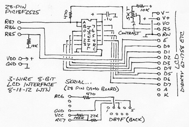
The serial port is just resistors to limit current flow, it's not proper but this kind of interface has always worked for me.. over the years tested with at least 4 PC's and with a cheap serial-USB converter. The 100K resistor pulls RC7 high when no port is connected to make it easy for software to detect if a serial connection is available. If using a proper (inverting) interface (MAX232, USB-serial TTL etc) then in the serialsetup function set the RXDTP and TXCKP bits to 0.
8/12/12 - Updated the app framework test program... now with serial input. The stdin stream is supposed to be connected to the serial character input function via getchar, but not sure if it's working or how to use it.. strncpy(string,*stdin,16) returns garbage and it doesn't recognize gets but that would be a very bad idea anyway. Instead I just wrote my own serial line input function that supports backspace (both ascii 8 and 127) and a character limit to avoid overflowing the buffer... extra characters are ignored. The serialin function for getting single characters takes a timeout parameter, if 0 then waits forever or can specify approximately how long to wait for the user to type something. This framework still needs some more testing (particularly the LCD stuff.. at the moment I don't have a module handy to connect to it - the code worked before and hasn't been changed so it should work), might still need some tweaks, but it's pretty much what I want - simple and to the point, kind of stuff I need to support the kinds of apps I write and without extra fluff. The idea is to have a starting point where I can just fill in the actual app code without having to do a bunch of hunting and copy/paste for infrastructure stuff.. just delete the stuff that's not needed for a specific app.
8/13/12 - Some more notes... This stuff is written for a Linux
install because that's what I use (presently Ubuntu 10.04), the
include paths assume SDCC is installed to /usr/local, edit if not.
Use SDCC version 3.2.0 or greater, downloads are
here. SDCC also requires the gputils
package, recommend version 0.14.2 but 0.13.7 works too. For
both SDCC and gputils, the Linux binaries are in the *-linux-x86
directory, Windows binaries are in the *-win32 directory. The
Linux SDCC binaries are just files in an archive, run a file
manager as root then copy the files under bin to /usr/local/bin
and the directory under share to /usr/local/share - or follow the
install instructions. Myself, I compiled SDCC from source, which
does require that gputils 0.14.2 be installed to compile the
libraries (0.13.7 doesn't support some newer chips) plus lots of
-dev packages. For gpasm, the Linux binaries are in rpm format and
not current, so compile from source to get the current version
(./configure and install -dev packages if/until it stops
complaining, then make then sudo make install) or install the
gputils-0.13.7 package present in most distro's repositories.
MPLAB-X downloads are presently
here. For the Linux version after downloading (make sure
Firefox is set to download and not run which is the default - I
had to fish it out of /tmp after it tried to run it and failed),
set the file properties to allow execution, drop to a terminal and
run the installer .run file using sudo. Installing the
MPLAB-X/SDCC system under Linux wasn't exactly point-and-click,
but not that difficult.
For Windows 7, it was pretty much point and click - downloaded
exe installers for SDCC 3.2.0a, gputils 0.14.2 and MPLAB-X, ran
the gputils installer, then the SDCC installer, then the MPLAB-X
installer (uncheck the box at the end to download compilers),
created a new SDCC project, in the SDCC setup checked use
non-free, added libc18f.lib and libm18f.lib to the extra options
line, and although probably not needed in the PIC16 options
selected large and some optimizations. Pasted in the source code
for the framework test, edited the include lines to replace
"/usr/local/share/sdcc/include/pic16/" with "C:\Program
Files\SDCC\include\pic16\", code compiles fine (didn't burn but
surely that's fine too), the IDE shows no error flags other than
the short putchar function with __wparam (ignore). One little
glitch though... for directly viewing or editing code outside the
IDE, might want to get an editor besides notepad - it can't handle
files with LF line ends like MPLAB-X, Linux and many other tools
produce.
8/17/12 - Browsing through some parts of the internet that deal
with embedded tools and technology - like the comp.arch.embedded
newsgroup or the Microchip
forums - can be very helpful, but can also be very
misleading unless the reader remembers that those who post are
posting their opinions and observations based on their own
experiences and while useful, the posts don't necessarily
represent the general case. Same can be said about this site... I
document what works for me. In the case of software forums,
remember that usually people come to those places when something
doesn't work - it's rare to see a post simply saying someone used
the software and it worked fine. I use the forums to identify
things that don't work and incorrect ways to do things.. someone
has an issue, often makes a big deal out of it, then upon detailed
examination often it's because the user assumes the software
should work in some particular way but doesn't, is trying to do
something "odd", or didn't RTFM. Lots of users are having issues
with MPLAB-X, which does have some bugs but I'm not familiar with
earlier versions of MPLAB, and tend to keep things simple and
functional (building the complexity from simple known-to-work
things). When I run into an issue I research it and usually find
out it's because I was doing something wrong or just work around
the issue (like making MPLAB-X work with SDCC), so it works fine
for me. On the other hand.. the forums concerning the Hi-tech C,
C18 and XC8 compilers were very helpful to me, and mostly match my
experiences.. HTC seems to work fine, haven't worked enough with
C18 to have an opinion, and XC8 still needs a lot of work - had no
luck getting that one to work (but I haven't tried the new v1.10
update yet). My inclination based on my own experiences and the
postings, is to stick with HTC or use an open-source compiler
that's both reasonably compatible and specifically permits
commercial development - such as SDCC. True, SDCC is somewhat
bloated as it supports many processors and uses an intermediate
representation, and yes it has bugs too, but on non-trivial
programs it doesn't produce all that much bigger hex files than
produced by the free version of HTC, and language bugs tend to
affect all processors and tend to get noticed and either
documented or fixed. Bugs in the intermediate-to-target
translation tend to be just stuff that doesn't work and are easy
to avoid... I just use what works. Most of the documented SDCC
bugs I've read about are for things I have no desire or need to
do... another consideration is if I can't understand what a
particular chunk of code is supposed to do, I don't expect a
compiler to know either.
The newsgroups are another matter - everyone has an opinion and
there seems to be a tendency for people to think that their
thoughts are the one true way without consideration of the
uncountable other factors that determine what chip is most
suitable for a particular job. Today I read that the 8051 and PIC
architectures are "_amazingly_ awful". Which I somewhat agree with
as far as the instruction set - but that only matters when someone
is coding for them directly in assembly language, and as far as
PICs I'd apply that label only to the old 12-bit cores with banked
program memory, the newer 14-bit and 16-bit cores are just merely
"awful". On the other hand almost 20 years ago I wrote an app for
a PIC16C56 and that part family is still available and the app is
still being manufactured (not by me anymore, making dingaling
boxes for ice cream trucks got really old:-). Microchip tends to
make parts forever, whereas Atmel often drops parts once sales
drop off - as a circuit designer that means far more to me than
what the instruction set looks like and it is hard to predict
which new chips will be popular. I feel much safer using PICs. As
far as the 8051/8052, that's a mature technology and can be used
to make 8-bit processing systems with more capabilities than a
typical PIC or AVR - here's a 32KB 24-IO
Paulmon-based design I put together over a decade ago (sorry
about the bad-quality schematic, all I have) - but yes, it's very
outdated.. newer 805x-based parts are available but the AT89C52 I
used is difficult to impossible to get, let alone one burned with
Paulmon.
That's an old page - getting it used to be "no problem"... until
Atmel dropped the part. That sure was a nice system, not only was
Paulmon a bootloader but also an operating system that let me have
multiple apps and utilities in memory at once. But now dozens of
projects on the web.. including some on my pages.. no longer can
be implemented. THIS is why I hesitate to use Atmel for anything
important. Yes, the ATMega series is still going strong, used by
the Arduino, roughly equivalent in capabilities (+/-50%) to PIC18F
parts like the PIC18F2525 I like to use. But will it be around 10
years from now? Can I use the tool software to develop commercial
apps? Definitely not the Arduino IDE, and avr-libc for gcc is
problematic (BSD.. but ANY license much beyond WTFPL is often an issue for
embedded).. not sure what that leaves other than Windows-based
commercial tools. Seems like everywhere I look in the embedded
world it's the same old stories - too complicated for what I need,
too many restrictions on what I can do with my creations, requires
Windows, chips go out of date.... except for PICs. So I use what
works.
These are my considerations, based on my needs... but certainly
are not universal. For a Windows user Windows software is an
advantage. Many products need parts for only a few years, not the
10+ years or so I like to see stuff remain available. Commercial
compilers and dev systems are no problem for large companies and
for hobby apps the license doesn't matter. For complex apps you
need a complex 32-bit part. Everyone has at least somewhat
different needs and embedded apps range from flashing an LED to
apps that need full-fledged operating systems - there is no
one-size-fits-all. So... yea that tired phrase but it's so true.
The trick for newcomers is to discover what works best for
whatever needs doing.
PC Programming
12/30/12 - "Use What Works" definitely applies to making PC
programs. In particular, making small utilities that need to be
very reliable when one is not exactly a PC programmer and has no
desire to be one other than being able to accomplish whatever
needs doing. I know enough about modern programming techniques to
be able to configure and compile the software I need, be it SDCC
or whatever, and if needed, dive into the source code to fix or
add something or just trace how something works (the less of that
kind of stuff I have to do the better.. but for critical stuff
like compilers I feel better if it is at least possible). Modern
software is often extremely complicated with many thousands of
lines of code scattered over dozens of files with many
dependencies and sometimes complex build procedures, but thanks to
GNU/Linux, gcc and package systems like Synaptic it's usually just
a matter of doing ./configure and installing -dev packages until
it completes without complaining then doing make and if needed
sudo make install... the process is fairly standardized. For less
critical software can usually just grab a binary package and
install it but it's nice to be as independent as possible, to be a
master over the software I depend on. Building software under
Windows is another story.. if something works under Cygwin then
great but if not I'm pretty much stuck running pre-compiled
binaries. Fortunately for me I only need to use Windows for
running stuff that doesn't work under Linux like Altium Designer,
and for testing stuff. However, it is still a Windows world so
when I do make utilities and toys it's kind of important that the
stuff works under both Linux and Windows, and since I'm not
exactly a PC programmer (not in the modern sense), I need
something that's cross-platform, easy and fast so I can focus on
whatever needs doing and less on how to implement it.
For me the solution is FreeBASIC.
It comes in Windows and Linux versions, the Windows version works
under wine so I don't have to boot into Windows to cross-compile,
usually the same source compiles and works the same under either
platform, it supports graphics (at least up to 640x480 but that's
good enough for what I need - usually I just need console apps),
it compiles to assembly and is extremely fast, there are few
dependencies (the main dependency is 32 bit libraries -
"ia32-libs" - when running on a 64-bit Linux system but I use lots
of stuff that needs that), and most of all, it implements a
language that I'm used to so I don't have to constantly hunt for a
solution. One of the options is good old fashioned QBasic, a
language I've been using for about 20 years, and not that
different from other dialects of BASIC especially when I stick to
simple stuff. A lot of people hate BASIC, I get that, but when it
solves the problems I need to solve whether it's making a
recreational toy or a compiler I need to depend on, I don't care.
I use what works for me, and works for the other people that have
to use the stuff (normal people just use the binary and don't care
what language it's written in so long as it works). One of the
most critical programs I use is my SIMPLE compiler for PIC12 and
PIC16 chips, I've used it for about 12 years under (now emulated)
dos but recently updated it to use
FreeBASIC and gpasm/mpasm to make a version that works natively
under Windows or Linux. It's critical because the kinds of things
I write with it typically go into small PIC chips that are
soldered to a PCB, the only way to update the code is to recall
and replace the chip. For stuff like that I simply cannot tolerate
state-of-the-art and all the complexity and bugs that brings -
that's why it's called SIMPLE. And it's just a few hundred lines
of QBasic-style code. Mostly for fun and as a test before
committing the new version to production use, I used SIMPLE2 to
implement an interpreter for
PIC16 chips that runs byte-code produced by a compiler written using QBasic-style
code. The SIMPLE2 compiler worked great, no changes indicated by
the process. Yet as I write this web code I find that SeaMonkey
Composer won't let me make the links (had to close and restart
it), and throughout the coding process I had to deal with Gedit
randomly corrupting line-ends causing extra blank lines when
converted to crlf format (so Windows users can read the code in
Notepad). I respect and study structured programming methods but
I'm not exactly keen on letting that stuff into my nice
deterministic world where programs usually do exactly what I tell
them to do, and when they don't they're trivial to fix once the
problem is noticed.
To be fair, the bugs in modern programs are due to their
complexity, not the programming methods... but that's kind of the
point - using structured programming methods for simple programs
often makes those programs more complicated and more likely to
contain bugs, for no real benefit (the benefit comes when programs
are huge). As with almost everything, there are advantages and
disadvantages to different approaches - in the case of
QBasic-style coding (at least the way I do it) it's only good for
relatively small programs, over a few thousand lines it can get
unmanageable. The next step up for me in BASIC-land is the native
FreeBASIC syntax, which supports proper procedures and requires
that variables be delared before using (a common QBasic bug is
misspelling a variable name and instead creating a new variable).
An example of native FreeBASIC is this corewar program evolver I
wrote about 3 years ago. At the time I had to use a workaround to
avoid using the shell command under Linux but that compiler bug
has since been fixed. Another not-so-great example is this serial terminal emulator I made for
using with the HLLPIC interpreter - no goto commands but
navigating all the nested loops and conditions is tedious
(fortunately it's small), sometimes I find it easier to maintain
and modify code when it's written as a flat multi-branching
program, then I can just add the code I need without having to
fight the existing structure because there isn't much structure to
begin with. Both SIMPLE and the HLLCOMP compiler for HLLPIC have
been extensively modified since their creation (well over a decade
ago) yet it's not an issue. One really nice thing about using
archaic methods is I don't have to worry about a committee
changing the language specs and breaking my code, the specs are
essentially written in stone. There will likely come a day when I
have to use C or another structured language to write PC stuff
from scratch, not looking forward to it but when/if it happens I
need to remember to not be attracted to shiny things so my stuff
will have a fighting chance of my code still working down the
road.
GCC on an AVR versus SDCC on a
PIC
10/27/15 - The debate rages on it seems anytime someone mentions
a PIC on the newsgroups, someone always has to point out how bad
PIC's are, how the AVR tool chain is superior to SDCC and other
PIC compilers. The things they say are (mostly) true, but it
doesn't change the fact that more often than not something like a
PIC18F2525 is a better match to the types of apps I need to make
(at least those I'd be programming in C) than either a ATMEGA328
(too small) or a ATMEGA644 or 1284 (too big). GCC/AVR does look
nice, but avr-libc is out (BSD restrictions) and most of the
advantages of GCC are for things I don't care that much about -
newer standards (C90 is good enough), memory segments (SDCC and
I'd hope GCC automatically put string constants in flash and other
constants can be defines), dynamic allocation (don't do that,
local variables are already dynamic unless told otherwise), high
execution speed (the speed of an app is limited by the stuff it's
controlling, not the processor), etc. One thing that sometimes
matters is the compiled code size (the apps don't need to be super
fast but they do have to fit in the chip). SDCC optimizes some
things fairly well - the line "if (var1&4) var2=var2|0x80;"
emits 3 single-word instructions if no bank selects are involved,
for other things (like library calls) not so well. The thing that
always matters is reliability - if a compiler emits incorrect code
even once (and it's not my fault) then it's hard to trust it for
anything - but both GCC and SDCC are mature projects that are
likely very reliable so long as one sticks to the basics, and if
in doubt one can check the assembly listing. Both compile to
intermediate code first so fixes to the base compiler apply to all
supported devices, ports just have to get the
device-specific backend right.
But how does the final code size of a SDCC/PIC app really compare
to a GCC/AVR app?
The Arduino prototype code was 541 lines of source that produced
8288 bytes of object code, the shipping PIC18F version was 1441
lines of source that produced 26018 bytes of object code. 8288/541
= 15.32, 26018/1441 = 18.06 - pretty darn close! But that included
comments and blank lines, so computed again using 4 metrics -
sloccount from the sloccount program, the size of the source code
with all white space removed, the number of words and operations
in the source, and the nc-lines count from the complexity program.
The source size was determined using the following command...
cat *.c|grep -v "^#"|sed 's/\/\/.*$//g'|tr -d '[:space:]'|wc -c
The number of code words/ops was determined using the following
script...
-------------- codewordcount -----------------------------------------------
#!/bin/bash
# estimate C code complexity by counting the number of operations
# ignores lines starting with #, ignores anything on a line after //
# count " [ ] == ++ -- + - * / >> << & | <= >= < = > !> && || as
# single words, this makes += -= count as 2 words
# ; , ( ) { } don't count at all
if [ ! -e "$1" ];then echo "file not specified";exit;fi
cat "$1"|grep -v "^#"|sed 's/\/\/.*$//g'|\
sed 's/{/ /g'|sed 's/}/ /g'|sed 's/\[/ a /g'|sed 's/\]/ a /g'|\
sed 's/\"/ /g'|sed 's/==/ eq /g'|sed 's/++/ pp /g'|sed 's/--/ mm /g'|\
sed 's/+/ p /g'|sed 's/-/ m /g'|sed 's/*/ t /g'|sed 's/\// d /g'|\
sed 's/>>/ rs /g'|sed 's/<</ ls /g'|sed 's/&/ a /g'|sed 's/|/ o /g'|\
sed 's/<=/ le /g'|sed 's/>=/ ge /g'|sed 's/</ l /g'|sed 's/=/ e /g'|\
sed 's/>/ g /g'|sed 's/!=/ ne /g'|sed 's/&&/ la /g'|sed 's/||/ lo /g'|\
sed 's/;/ /g'|sed 's/(/ /g'|sed 's/)/ /g'|sed 's/,/ /g'|wc -w
--------------- end codewordcount ------------------------------------------
Both of these methods assume //-style comments, but that's what I
used. The efficency ratio was then determined by dividing the
binary size with the number returned by each method. Here are the
results...
                   GCC/Arduino       SDCC/PIC18F      SDCC/GCC ratio
obj/sloccount    8288/435=19.05   26018/1133=22.96        1.205
obj/src ratio    8288/7618=1.09   26018/21296=1.22        1.119
obj/code words   8288/1342=6.18   26018/3423=7.60         1.230
obj/nc-lines     8288/352=23.55   26018/841=30.94         1.314
Well then... not seeing any huge inefficiencies here. According
to the assembly listing the SDCC-produced code from the C source
was 14918 bytes, so 11100 bytes of the binary is library code. The
Arduino compiler didn't provide an assembly listing so don't know
how much of it was library code but clearly the avr-libc and
Arduino library code is a lot smaller.
Another PIC18F2525-based speaker tester app I recently made was
bigger and used a lot of string prints, inflating the by-line
numbers, but still it's another data point to compare. The source
program was 1724 lines, producing a 43994 byte object, of which
16994 bytes was library code - pretty much at the limit of what I
can pull off on a '2525 using SDCC. Here's how that came out...
                   GCC/Arduino       SDCC/PIC18F      SDCC/GCC ratio
obj/sloccount    8288/435=19.05   43994/1503=29.27        1.536
obj/src ratio    8288/7618=1.09   43994/33669=1.31        1.202
obj/code words   8288/1342=6.18   43994/5472=8.04         1.301
obj/nc-lines     8288/352=23.55   43994/1179=37.31        1.584
Not drawing any hard conclusions without knowing what proportion
of the Arduino code was library code, but the data shows about
approximately how efficient SDCC is at translating C code into
object code. The obj/code words metric is probably a somewhat more
accurate estimate as it's insensitive to name lengths and how many
statements are on each line.. but who knows. Not being able to use
avr-libc will likely increase the binary size... in the Arduino
version replacing all the Serial.write commands with
__builtin_printf increased the binary size to 9480 bytes, not too
bad but lessened the gap. Regardless, SDCC can be used to create
fairly large commercial PIC18F apps and personally I've had no
real issues with it other than learning to not use the
known-unreliable --obanksel option. It's not the most efficient
PIC C compiler (that would probably be CPIK) but it gets the job
done.
11/4/12 - A couple of months ago I delivered a prototype of the
PIC-based product that triggered all this C compiler stuff... so
far so good. MPLAB-X and SDCC running under Linux got the job done
with no tool bugs other than the IDE workarounds I covered above -
essentially specifying the full path for include files to avoid
(non) error highlights, and using a stub function for putchar
(MPLAB-X doesn't know about __wparam) to avoid error-flagging the
whole output function. There was a discrepency in the mscalibrate
value but I'm pretty sure for SDCC the correct value should be
176... as often is the case when developing product prototypes
there wasn't a whole lot of time for experimenting. I can't say
too much at this time about this particular app (it's for a
client) [now I can... it's a headset
tester] but it involved using ohms law to calculate
resistance by injecting a small current and displaying the reading
on an LCD, but in the presence of a much larger audio signal so
lots of averaging was needed. Fortunately the display didn't have
to be updated too frequently.
I'm using the MPLAB-X options: optimize compares, optimize data
flow, use non-free, small stack, with libc18f.lib and libm18f.lib
for additional options. This is equivalent to the following
command line...
sdcc -mpic16 -p18f2525 --optimize-cmp --optimize-df --use-non-free libc18f.lib libm18f.lib app.c
Replace app.c with the actual app source filename. Or in
script form (named compile_sdcc18)...
#!/bin/bash
sdcc -mpic16 -p18f2525 --optimize-cmp --optimize-df --use-non-free libc18f.lib libm18f.lib "$*"
[removed the --obanksel=2 options from these, saves about 3% but
bank optimization is risky and can cause bugs, the manual warns
about that]
To burn the resulting hex file into a PIC with its own power
supply I can use the following script (named burn18_ext)...
#!/bin/bash
# erase PIC and burn hex file - device powered
pk2cmd -W -K -R -P -M -Z -F "$1"
...or just do it from the MPLAB-X IDE, which uses the PICKit 2
programmer to auto-detect device power.
In my app hardware, the externally-available reset, RB6 and RB7
programming lines are protected using 0603 MOV's (DigiKey
#F2199CT-ND) with 10 ohm series resistors on either side for a bit
of current limiting, the MOV's have about 80pF capacitance but no
problems with in-circuit programming. The hardware uses the same
3-wire LCD interface and a variation of the driver code presented
here, plus a bunch of opamps, transistor switches and other stuff
for measuring voltages, activating circuits and displaying info in
response to the readings. Doesn't need fast processing so running
the PIC at 8mhz to keep the current drain reasonably low.
Originally I wrote the app code in HiTech C (well, actually
Arduino but that didn't work out), but soon converted it to SDCC
as HiTech C is no longer supported by Microchip, so far I've had
no luck getting the replacement (XC8) to work, and I'd rather use
a compiler for which I have source code in case I have to fix
something myself. SDCC is not perfect - but the bones of the
compiler is used for many chips and is well-tested... parsing and
other major errors tend to be quickly noticed and fixed (or
documented) so mainly I just have to watch out for PIC18-specific
code translation bugs (and making sure I don't exceed the call
limit for small stack size). This approach isn't as efficient but
in my opinion the increased reliability makes up for the slower
speed and increased code size - for most of the things I do speed
really does not matter (my apps tend to spend 90+% of the time in
delay loops), and my current app is only using about half of the
available 48KB rom, and a fair chunk of that is for fixed-size
library code... the actual app could triple in size and still fit.
On the other hand, HTC and XC8 have serious bugs - HTC bugs are
subtle and are no longer fixed (I had no problems but other users
report weird stuff), and I couldn't get XC8 to even do simple
stuff like setting port B pin states correctly. In the real world,
I am responsible for the code I make... if there's a bug that
could mean a recall, so I'm inclined to use open software like
SDCC, it may not be perfect but at its imperfections are not
hidden and can be understood.
Frankly, this C stuff for embedded scares me - the more complicated a language or compiler is, the greater the chances of bugs. I've seen some rather severe bugs in embedded products that smell like pointer issues, for example early versions of the VDRIVE firmware that would very occasionally return data from the command buffer rather than the flash device.. oops. But for apps that need to be written in a high-level language, particularly apps requiring floating-point math, it looks like C is the most practical choice. However I'll treat it like it was BASIC... literally stick to the basics. It might make my code look primitive but working with no surprizes is far more important to me than style.
I need a good bread-board-capable PIC18F processor module for prototyping and testing...
PIC18F2525 processor w/ internal clock (up to 32mhz, 1% accuracy)
8 pin socket for external oscillator, pads for a crytal and
capacitors or resonator
2 line LCD connected to RB5-RB7 using the 74HC164 circuit
Transistor on RA4 for controlling LCD backlight
DB9 serial port connected to RC6,RC7 using resistors (logic
inverted from normal serial)
LCD and DB9 on breakaway parts or separate plug-in boards for apps
that just need a processor
6-pin header for attaching a stock USB-logic (non-inverted) serial
adapter (i.e. DK# 768-1028-ND)
6-pin header for connecting a PICKIT 2 or another in-circuit
programmer
All PIC lines brought out to wire-capable 0.1" connectors
5V powered with an integrated/jumpered LDO regulator for 9V
operation
...one day... would be handy to not have to perf something up
every time I need to test some code.
Something like this is good for midrange embedded apps.. far less
than a MP3 player or something needing an actual operating system
(there are plenty of ARM-based dev boards for stuff like that),
but typical of many process control apps with a dozen or so I/O
lines, often with analog inputs that need calculations to control
other stuff. At a much lower end of the spectrum are apps that
only need a tiny 8-pin processor like the PIC12F629 or PIC12F675
(with analog), or for more I/O, the 14-pin PIC16F684. I've got at
least 3 immediate projects like that... one is for controlling a
single-cell power supply where the boost regulator has to run all
the time (has to be extremely low power), another that just needs
to output an encoded signal when switches are changed to control
something else, and another project I'm helping with that simply
needs to divide a clock to provide precise pulses with a reset
input. For stuff like this I use the dos-based Techtools CVASM16
assembler, the classic PICKIT 1 programmer/dev board with a SOIC-8
adapter, and if I need a HLL then I (still) use my homemade SIMPLE
compiler which doesn't do much more than keep track of
if/then/else levels and translate strings into CVASM16-compatible
assembly. For these kinds of apps I don't need or want much from
the language, rather I need precise mapping from the source to the
actual code, especially when I have to count cycles. I tried to do
the last counter project using MPLAB-X and MPASM, got precisely
nowhere - all it would tell me is the makefile target not defined
with not a clue as to how to fix it. All that IDE makefile library
etc stuff is needed to deal with C but it totally fell over when
asked to do something braindead-simple - so back to dos(emu), it
works.
For that last app I needed to generate precise cycle delays using
code like...
        movlw ConstantC
        movwf CounterC
loop2   movlw ConstantB
        movwf CounterB
loop1   movlw ConstantA
        movwf CounterA
loop0   btfsc someinputpin
        goto somewhereelse
        decfsz CounterA,1
        goto loop0
        decfsz CounterB,1
        goto loop1
        decfsz CounterC,1
        goto loop2
The problem was how to determine values for the constants that
would give me the delay I needed, close enough to pad with a few
nops. Well... the inner loop TimeA=(ConstantA*5)-1 cycles,
TimeB=(TimeA+5)*ConstantB-1, TotalTime=(TimeB+5)*ConstantC+1. Not
sure how one would go about directly translating a specific number
of cycles to constants, so instead I wrote a simple BASIC program
that solved it by brute force...
again:
PRINT "1) manual  2) auto"
INPUT z
IF z = 1 THEN GOTO manual
IF z = 2 THEN GOTO autocalc
GOTO again

manual:
INPUT "Counter A ", CounterA
INPUT "Counter B ", CounterB
INPUT "Counter C ", CounterC
GOSUB calc
PRINT timeC
GOTO again

autocalc:
INPUT "desired ", desired
INPUT "allowed under ", under
FOR CounterA = 1 TO 255
FOR CounterB = 1 TO 255
FOR CounterC = 1 TO 255
GOSUB calc
IF timeC < (desired - under) THEN GOTO nope
IF timeC > desired THEN GOTO nope
PRINT "A="; CounterA, "B="; CounterB, "C="; CounterC, "T="; timeC
nope:
NEXT CounterC
NEXT CounterB
NEXT CounterA
GOTO again

calc:
timeA = CounterA * 5 - 1
timeB = (timeA + 5) * CounterB - 1
timeC = (timeB + 5) * CounterC + 1
RETURN
Crude but effective, tries every combination and lists the ones
that are within the specified under amount. First ran it under
QBasic but it's much faster if run under blassic, just insert
"label " before each of the labels. There is no exit, control-C to
quit. To verify the timing of the PIC code, first tried using
MPLAB-X but couldn't figure out how to make it output the number
of elapsed cycles when it hit a breakpoint. Tried a couple of
other PIC simulators that were interesting but they didn't do what
I needed. Ended up using the command line gpsim program - load
pic12f629 app.hex, then break e address of the pulse code, run,
run, run etc and used a calculator to subtract the hex cycle times
and convert to decimal to make sure it was exactly the number of
cycles I needed.
11/6/12 - Modern versus Old... I'm kind of miffed that MPLAB-X
failed so completely when I tried to use it to assemble something
for a PIC12 part, but it's probably an install problem specific to
my machine (surely such a fundamental issue would be noticed...
but who knows maybe not) [update... turns out that the default
".s" extension for assembly files won't work, must change to ".asm
or ".ASM"]. MPLAB-X 1.50 is out, so trying that... oh the horror,
it can't open my current C project - just keeps spinning and if
anything is clicked throws a Java null pointer exeption. OK so
much for that, it is becoming obvious that using commercial
development software under Linux is probably not a viable option -
looks pretty and all that but fails in the actually working
department. Back to v1.41. Regardless, I don't really "need" an
IDE (it's just nice), SDCC works fine from a command line under
Linux or Windows so I don't need to worry too much about being
able to compile C code for a PIC18... it's modern enough and it
gets the job done. But I really need to update my PIC12/PIC16
tools - being dos-based there is no telling how much longer the
tools will remain available or be runnable. For pure assembly,
gpasm works. The syntax is somewhat different than the CVASM16
assembler, it doesn't support Parallax instructions, have to add
errorlevel -302 to suppress goofy bank warnings, but it works.
Now I just need a modern replacement for SIMPLE... done!
It's still mostly like the old dos SIMPLE, just converted to
output gpasm/MPASM-style code instead of CVASM16/Parallax-style
code. Which wasn't exactly easy but fortunately I still have my
"PIC16Cxx Development Tools" book that came with the original
Parallax assembler (from almost 20 years ago) with the mappings to
Microchip instructions. Here's what I have so far... [updated as
needed]
Files have .txt added for web compatibility. The source code
isn't pretty, it is written in the almost simplest way possible to
minimize the chances of bugs and make it easy (for me:-) to trace
code execution paths. Essentially it just reads the source line by
line with a table of GOTO statements to generate the code with as
little state-dependence as possible. The SIMPLE source is included
in the output code other than trivial conversions.
Usage... write simple source code in a text file, run simple2
source.ext to produce source.asm (or specify output file too), run
gpasm source.asm to produce a hex and lst file, burn the hex into
the PIC using PIC-programming software (I use usb-pickit with a
PicKit 1). Run simple2 --help for a summary of the language but it
doesn't include the other needed stuff like the proper asm include
and other assembler-specific options, refer to the include file
for the specific chip for the proper register names.
I gave it a pretty good workout with the test program, but it
definitely needs more testing before I consider it
production-ready (will update as needed, if anyone notices a bug
or does something neat with it please let me know)... but going
ahead and posting it now so I won't be tempted to waste too much
time messing with it - language-wise it does what I need. Sure it
would be nicer if it had true FOR var = bla to bla or WHILE WEND
etc but those kinds of things can easily be simulated with what it
has and the more features are added, the greater the chance of
getting something wrong. It only supports 9 levels of if or loop
nesting to keep the labels simple, that should be plenty
(otherwise probably over-bloating it with structure). The language
was designed for doing simple control tasks without having to
think much about how to express it... but a couple things - math
expressions must be simple, one step at a time, and if the output
references itself the reference must be first - VarA = VarA + VarB
(otherwise VarB overwrites the previous value of VarA). All
numbers are considered literal values whether or not preceded by
#, to reference absolute ram/register locations use define to fool
it. If a defined value is supposed to be a constant then precede
with # when used, not when defined. Unlike most other compilers,
SIMPLE knows nothing about chips or valid names or labels,
anything needed to make the program assemble must be included in
asm or raw statements and it relies on the assembler for most
syntax checking. This simplicity also makes it possible to compile
incomplete chunks of code which can be pasted into other assembly
programs.
11/7/12 - Here are a couple scripts I'm using to integrate
simple2 and gpasm into my Gnome GUI...
This script compiles a file with simple2 and if an asm file is
produced, assembles it with gpasm to produce hex and lst files...
#!/bin/bash
# Compile_Simple2
# associate with ".sim" files to compile/assemble by right-click
if [ "$2" = "doit" ];then
 dn=`dirname $1`
 fn=`basename $1`
 bn=`echo $fn | cut -f 1 -d .`
 if [ -e $dn/$bn.asm ];then rm $dn/$bn.asm;fi
 if [ -e $dn/$bn.lst ];then rm $dn/$bn.lst;fi
 if [ -e $dn/$bn.hex ];then rm $dn/$bn.hex;fi
 echo "Compiling $fn with simple2 to $bn.asm ..."
 simple2 $1 $dn/$bn.asm
 if [ -e $dn/$bn.asm ];then
  echo "Assembling $bn.asm with gpasm -i to $bn.hex ..."
  gpasm -i -n $dn/$bn.asm -o $dn/$bn.hex
 fi
 if [ -e $dn/$bn.cod ];then rm $dn/$bn.cod;fi
 echo --- press a key ---
 read -n 1 nothing
else
 if [ -f "$1" ];then
  if [ -f $1 ];then xterm -e $0 $1 doit;fi
 fi
fi
This script assembles a file with gpasm to produce hex and lst
files...
#!/bin/bash
# Assemble_gpasm
# associate with ".asm" files to assemble by right-click
if [ "$2" = "doit" ];then
 dn=`dirname $1`
 fn=`basename $1`
 bn=`echo $fn | cut -f 1 -d .`
 if [ -e $dn/$bn.lst ];then rm $dn/$bn.lst;fi
 if [ -e $dn/$bn.hex ];then rm $dn/$bn.hex;fi
 echo "Assembling $fn with gpasm -i to $bn.hex ..."
 gpasm -i -n $1 -o $dn/$bn.hex
 if [ -e $dn/$bn.cod ];then rm $dn/$bn.cod;fi
 echo --- press a key ---
 read -n 1 nothing
else
 if [ -f "$1" ];then
  if [ -f $1 ];then xterm -e $0 $1 doit;fi
 fi
fi
Both scripts use xterm to display output (edit to use another
terminal), and remove the output files before running. Output
files have the same base name as the source file with the
extension replaced with (asm) lst and hex extensions.
11/8/12 - Aha - I knew odds were there'd be a bug somewhere..
sure enough a somewhat more complete comparison
test
program found a stupid typo that was causing the if var
<= constant form to always branch, fixed. Score one for
testing... but still rating it as not completely tested yet. This
crude little compiler (if it can even be called a compiler, it's
closer to being just a more readable version of machine code)
certainly isn't for everyone (or maybe even for anyone besides me)
but it has one huge advantage over most other compilers: other
than if/then/else/endif and loop/next label generation, and
assigning ram locations, it is practically stateless. Each line of
code directly translates to a sequence of machine code
instructions without depending on any other lines, so once a
particular instruction form has been tested (barring really weird
bugs) that form will always produce the same code. The
disadvantage of that approach is it makes it impossible to check
for incorrect variables, labels, nesting, etc in the compiler
itself but for my usages that's fine, the assembler catches all
that stuff. The goal is for there to be 0 bugs in the compiler..
only extremely simple programs can even hope to achieve that. The
way this compiler is written would probably drive a programming
language purist crazy but part of the process is to also use only
the simplest of programming methods - it's hard enough to prove
there isn't a typo without the added complication of worrying
about a bug in the structure. The idea is to minimize the number
of possible branches to minimize the amount of code needed to test
every path, and right or wrong it is easier for me to visualize
all the paths by using a bunch of gotos rather than deeply nested
ifs in an attempt to avoid using goto - which seems to be to be a
rather artificial goal that simply hides the gotos instead of just
spelling them out. Structure has its place - for most software it
is better to have structure to avoid bugs caused by spaghetti
typos, but when it comes to testing every possible code path, that
is not necessarily true.
11/9/12 - Got MPLAB-X (v1.41) working for assembly - the critical
"error" on my part was going with it when it offered to use the
extension ".s" for assembly source files, when I change it to
".asm" or ".ASM" when creating the source file then it works. Of
course the rename option only renames the base name, not the
extension. The include filename and all register and bit names
must be uppercase, although the IDE thinks lowercase is OK. An
initial ORG is required.
11/11/12 - I've been doing quite a bit of simple2 compiler
testing - so far so good. Only bugs found was it wouldn't let me
use a ")" at the end of a constant expression to be processed by
the assembler (triggered the array read code), fixed that, and it
wasn't clear that array elements were numbered starting at 0 so
clarified in the help text (I almost never use the array feature,
mistakenly thought it numbered from 1).. updated the posted source
code. The crude parser doesn't do a lot in the way of syntax
checks, if fed bad source usually it silently generates bad
assembly but that's ok, the assembler catches it and the embedded
simple source in the assembly listing shows me the problem line.
It definitely could use a better parser but my main concern is
accidently introducing a parse bug that causes correct code to
fail - so I'm inclined to leave it alone other than fixing real
bugs as encountered.. I've used the original version for over a
decade and never had any issues with bad syntax slipping past the
assembler. [...working on packaging...]
11/12/12 - Posted binary packages for Linux and Windows builds of
the simple2 compiler, including documentation and PIC12F675
examples. Presently the examples are similar to the "blink.sim"
example - do a bunch of stuff and if no error occurs flash an LED
- but the stuff covers just about all of the language and includes
subroutines for reading and writing eeprom, 16-bit add, subtract
and shifts, and reading the '675's analog inputs (code for other
PICs is similar but different). The examples and docs still need
some work but so far the compiler itself checks out... [but not
quite...]
11/13/12 - Hammering it hard, nothing too major but found a few
parse bugs and doc errors.. updated again. Part of the process..
by publishing it forces me to test stuff I probably wouldn't take
the time to test, like indented asm's and mixed case nots. One new
feature... it now generates proper bit-flip code by doing bitcopy
bit = not bit where the two bits are the same, previously
if/then/else had to be used to flip a bit. Will keep hammering...
to replace my old tried-and-true dos version of SIMPLE this
(somewhat) modernized version needs to be solid as a rock.
8/24/20 [updated 12/13/22] - Here's a GTKSourceView language file for Simple2, it adds
highlighting when editing Simple source code with GEdit, Pluma and
other GTK-based text editors. Here's how it looks with the
"Cobalt" editor theme...
It's been almost 8 years since the last change to Simple2. I now use Simple2 for almost all of my PIC10, PIC12 and PIC16 projects, the last one used a tiny PIC10F222. Getting the old pk2cmd programming tool working again under Ubuntu 20.04 gave be a bit of trouble (solved by finding the source and recompiling) but the simple2 compiler never gave any trouble at all, still using the same 32-bit binary linked here.
11/17/12 - I was digging through some old stuff and found a SIMPLE-like interpreter I made in
1999 for small autonomous robot control.. it was basically a
virtual machine that executed opcodes from eeprom that implemented
a high level language.
I removed the robot-specific stuff from the original SIMBOT code,
converted the original Parallax-style assembly to SIMPLE2, then
added a menu-driven serial interface for loading and extracting
code to create the HLLPIC firmware for the PIC16F684 chip. All the
robot-specific and port-specific stuff was ripped out of the
original BOTEDIT program to turn it into a stand-alone compiler to
produce bytecode for loading into HLLPIC. The bytecode interpreter
is mostly still like the original but replaced the comments and
reserved opcodes for THEN ELSE and ENDIF (which will never happen
for various reasons - biggest being it's much more efficient to
fake stuff like that by generating GOTOs when compiling) and
replaced with INCREMENT and DECREMENT commands. To be functional
as a stand-alone controller I added a READANALOG command and
variables for specifying the channel and returning the results.
Lots of other little and not-so-little mods. The interpreter is
designed to run bytecode from a 24FC64 8Kbyte eeprom chip,
programs can be a maximum of 4KB because of the way GOTO and GOSUB
is encoded, so the rest of the eeprom is used for persistent data.
Commands can address up to 14 variables (A to N) with compact
encoding, or a byte-size address can be specified to reference ram
in the lower 256 bytes of memory (most of which is used for other
things), depending on the PIC used, from about 48 to 96 bytes of
ram can be used for extra variables and it provides full access to
the port and tri-state registers for reading and controlling PIC
pins. Execution speed isn't great, about 1000 to 2000 commands per
second depending on the clock speed and nature of the commands
(execution from the internal eeprom is about 3 times as fast).
These specs are certainly modest, it is not for running anything
that needs to go fast or needs fancy programming (for that use
assembly or a compiler), however it has the advantage of being
able to program it using a serial port (or USB serial adapter) and
fairly simple PC software. In the past there was a highly
successful "stamp" product with similar specs (give or take), and
the capabilities are adequate for the main app I want to use it
for - small robot control.
My main motivation for creating this thing is so when I make
things that need editable programming, that will be easy to do in
the future without having to depend on specific programming
hardware remaining operational... I have several old PIC
programmers that no longer work. With HLLPIC, all that's needed to
program the device is a user-accessible 9600 baud serial
connection and a PC can be programmed to run fairly simple
algorithms. Even without custom software I can still hand-assemble
the bytecode and type it in using a serial terminal.
Here are the main source files... (all have txt extensions added
for web compatibility)
Latest notes...
12/30/12 - Removed extra notes.. summarized in the code history
comments and updated the text below with the more important
changes.
The interpreter firmware and bytecode compiler now implement most
of the features I want for a system like this, at least for a
generic version - specific adaptations can have additional stuff
but I don't want the base system to be all that complicated. The
latest mods greatly improve the decompiler, the decompiler now
works on an entire 8KB eeprom dump without having to edit the
extracted bytes first. This is a fairly important feature for me,
in the past when I used a similar system for robot control
sometimes I forgot which program was currently loaded so I used
the decompile option to look inside - labels comments and defines
are lost but it is enough to tell what I had. I'm sure as I play
around with the system I'll find things to fix or improve, one fix
could be modifying the '690 version's readanalog command to work
with more than 8 channels.
6/30/14 - Packaged all this stuff into hllpic.zip
- includes Windows/Linux binaries/scripts, hex files, a copy of
SIMPLE2, the original SIMBOT stuff, and the original (impractical
but kind of neat) conversion for a PIC12F675 chip (mainly so when
I go looking for the stuff myself I can find it all in one place
without too much hunting.. but also to make it a stand-alone
expression of this work). I still want to eventually make some
kind of hobby robot app with this thing, but time....
Circuitry
The default PIC16F684 firmware assumes the parts are wired up
something like this...
      .----*------------*--*--*--*------------------*---10---o--< +5V
     _|_/  |    24LC64  |  |  |  |                  |        o--< ground
    //_\   |     __ __  |  | 10K *---0.1u----*--.  100K     _|_
      |   22K .-|  U  |-' 10K |  |   __ __   | _|_  |
     _|_   |  *-|     |-.  |  |  `--|  U  |--'      |          DB9F connector
  5.1V     |  *-|     |-|--|--*-----|     |--o------*---22K-----< pin 3 (Rx)
  zener    |  *-|_____|-|--*--------|     |--o-------*--2.2K----> pin 2 (Tx)
           | _|_       _|_    .--o--|     |------.   |       .--O pin 5 (gnd)
           |                  |   --|     |--    |  1K      _|_
    .--10--*-------------1K---'   --|     |--   1K   | LED1
  _|O      |                      --|_____|--    |   `--|>|--.
   |O     0.1u                                   |     LED2  |
   _|_    _|_                      PIC16F684     `------|>|--*
 Reset Sw.                         o=ISP connections        _|_
The optimal circuitry will vary depending on the app, this
schematic has a few extra parts (like the zener diode and 10 ohm
resistor in series with the supply) to help make it more
bullet-proof. Can be configured to eliminate the reset switch and
use that pin for another I/O but the reset switch provides easier
access to the serial menu, which in the present version only runs
if it is attached during a processor reset or power-on (unless
attached when an interpreter error occurs, then it dumps ram and
displays the menu to help figure out what went wrong). Note that
the ISP and serial in/out lines are on the same pins, so a single
5-pin header can serve as both a flash port or (with series
resistors) a serial port.
Most serial interfaces use an inverting chip to translate the
normally 12V serial levels, however I've been using a similar
resistor-based serial interface for years and so far haven't found
a PC or adapter it didn't work with. If desired the code can be
modified to invert the serial input and output states to use an
interface chip or a "USB/TTL" serial adapter.
The circuitry for the PIC16F690 version is similar, except that
the eeprom data pin (5) is connected to RB4 and the clock pin (6)
is connected to RB6. The PicKit 2 programmer loads RA0 enough to
keep the terminal from working, so the serial receive pin is
temporarily set to RB5 instead.
      .----*------*-------------------*--------*--*-*---10---o--< +5V
     _|_/  |      |                   |        |  | |        o--< ground
    //_\   |      *---0.1u----*--.   100K      |  |10K      _|_
      |   22K     |   __ __   | _|_   |        | 10K|
     _|_   |      `--|  U  |--'       |        |  | |          DB9F connector
  5.1V     |       --|     |--o .-----*--------|--|-|-----22K---< pin 3 (Rx)
  zener    |       --|     |--o-|--------------|--|-|--*--2.2K--> pin 2 (Tx)
    .--10--*--1K--o--|     |--  |       __ __  |  | |  |     .--O pin 5 (gnd)
  _|O      |       --|     |--  |    .-|  U  |-'  | | 1K    _|_
   |O     0.1u     --|     |--  |    *-|     |-.  | |  |LED1
   _|_    _|_      --|     |--  |    *-|     |-|--|-*  `-|>|-.
 Reset Sw.         --|     |----|-.  *-|_____|-|--* |       _|_
                   --|     |----' | _|_       _|_ | |
                   --|_____|--.   |    24FC64     | |
                              |   `---------------' |
                   PIC16F690  `---------------------'
About the compiler and the
HLLPIC firmware
Here's one of my test programs...
'test program - flash porta bits 1 and 2 randomly
'do some tests first to make sure it's working right
clear bit 2 of trisc 'make it an output
set bit 2 of portc   'should go high
a = 5 + 7 and 7  if a + 1 <> 101b goto testfailed
b = 130  if a > b goto testfailed
a = 5  b = 6  c = 9
if a + b >= b + c goto testfailed
if a + b > b + c goto testfailed
if b + c <= a + b goto testfailed
if b + c = a + b goto testfailed
if a + b <> 11 goto testfailed
if c - b = 3  goto testok0          goto testfailed
testok0: if a + b = 11 goto testok1 goto testfailed
testok1: if a < b goto testok2      goto testfailed
testok2: if a <= b - 1 goto testok3 goto testfailed
testok3: if b > a goto testok4      goto testfailed
testok4: if b >= a - 1 goto testok5 goto testfailed
testok5: if b <> a goto testok6     goto testfailed
testok6: a = 15  swapnibbles a  if a <> 11110000b goto testfailed
a = a or 1 + 1  if a <> 11110010b goto testfailed
invert a        if a <> 00001101b goto testfailed
set bit 1 of porta    clear bit 2 of porta  gosub delay
clear bit 1 of porta  set bit 2 of porta    gosub delay
testfailed: system
delay:  a = d xor rtcc  d = d + 1
delay1: b = 10  'make 2 or so for external ee
delay2: b = b - 1
if not zero goto delay2
a = a - 1   if not zero goto delay1
return
...which the hllcomp compiler turns into...
0000: 0E 2E 87 0E AE 07 10 4F 05 4F 07 6F 07 01 40 4F
0010: 01 0C 4F 05 20 C0 11 4F 82 01 40 07 41 20 C0 10
0020: 4F 05 11 4F 06 12 4F 09 01 40 41 0A 41 42 20 C0
0030: 01 40 41 07 41 42 20 C0 01 41 42 0B 40 41 20 C0
0040: 01 41 42 09 40 41 20 C0 01 40 41 0C 4F 0B 20 C0
0050: 01 42 51 09 4F 03 20 5A 20 C0 01 40 41 09 4F 0B
0060: 20 64 20 C0 01 40 08 41 20 6C 20 C0 01 40 0B 41
0070: 5F 01 20 76 20 C0 01 41 07 40 20 7E 20 C0 01 41
0080: 0A 40 5F 01 20 88 20 C0 01 41 0C 40 20 90 20 C0
0090: 10 4F 0F C0 01 40 0C 4F F0 20 C0 10 40 7F 01 4F
00A0: 01 01 40 0C 4F F2 20 C0 90 01 40 0C 4F 0D 20 C0
00B0: 0E 9E 05 0E 2E 05 30 C1 0E 1E 05 0E AE 05 30 C1
00C0: FF 10 43 8E 01 13 43 4F 01 11 4F 0A 11 41 5F 01
00D0: D5 20 CC 10 40 5F 01 D5 20 C9 0D
END
...which is loaded into the PIC's eeprom by using HLLPIC's serial
menu...
HLLPIC 1.12
P) Prog int
L) List int
X) Prog ext
Y) Dump ext
R) Run
>
[the '690 version has more menu options and can dump external ee
a page at a time]
It is not necessary to select a program command, if the menu is
showing just send the bytes file and it will be loaded into
internal or external eeprom depending on how the system is set up.
If internal eeprom locations FE,FF contain E4,EE then defaults to
external eeprom (the default with the stock firmware), otherwise
defaults to internal eeprom. If needed (say if no 24LC64 is
attached) the default can be changed using the P command... press
P then type FE:FF END to use internal eeprom, or type FE:E4 EE END
to default to external eeprom.
When uploading a program it looks like... (the X was printed by
the firmware to indicate loading to ext ee)
> X
0000: 0E.2E.87.0E.AE.07.10.4F.05.4F.07.6F.07.01.40.4F.
0010: 01.0C.4F.05.20.C0.11.4F.82.01.40.07.41.20.C0.10.
0020: 4F.05.11.4F.06.12.4F.09.01.40.41.0A.41.42.20.C0.
0030: 01.40.41.07.41.42.20.C0.01.41.42.0B.40.41.20.C0.
0040: 01.41.42.09.40.41.20.C0.01.40.41.0C.4F.0B.20.C0.
0050: 01.42.51.09.4F.03.20.5A.20.C0.01.40.41.09.4F.0B.
0060: 20.64.20.C0.01.40.08.41.20.6C.20.C0.01.40.0B.41.
0070: 5F.01.20.76.20.C0.01.41.07.40.20.7E.20.C0.01.41.
0080: 0A.40.5F.01.20.88.20.C0.01.41.0C.40.20.90.20.C0.
0090: 10.4F.0F.C0.01.40.0C.4F.F0.20.C0.10.40.7F.01.4F.
00A0: 01.01.40.0C.4F.F2.20.C0.90.01.40.0C.4F.0D.20.C0.
00B0: 0E.9E.05.0E.2E.05.30.C1.0E.1E.05.0E.AE.05.30.C1.
00C0: FF.10.43.8E.01.13.43.4F.01.11.4F.0A.11.41.5F.01.
00D0: D5.20.CC.10.40.5F.01.D5.20.C9.0D.
END
P) Prog int
L) List int
X) Prog ext
Y) Dump ext
R) Run
>
A dot is printed after each hex byte is programmed, an app can
wait for it before sending the next byte, or insert 12-20ms delay
after each character to allow for programming and echo time. The L
and Y commands for listing eeprom contents output everything.. 256
bytes for internal and all 8192 bytes for external... trying to
keep things simple, to list just part of the external eeprom just
press the reset button. The R command (obviously) runs the program
that was just loaded. It's not shown as an option, but pressing Z
from the menu lists the first (or only) 256 bytes of the PIC's
ram, and the ram dump is automatically performed if an error
occurs when a terminal is attached. This is useful for debugging
by examining the interpreter's variables etc, error dumps can be
forced by inserting CODE D7 (or any unimplemented opcode) into the
program.
If you know what you are doing, it is possible to write programs
directly in bytecode using only a terminal, but it's lots easier
to use the compiler. The language is very simple, run hllcomp
-help to print a summary of the commands. While simple (and slow)
the language still permits accessing any byte or register (where
it makes sense) in the first 256 bytes of ram by specifying
(location), for example (8Fh) = 01110000b causes the PIC to run at
8mhz instead of the default 4mhz. Many of the instructions that
reference memory or values use the low nibble of the instruction
to encode either 14 reserved variables (labeled A-N but can use
define to give them more descriptive names), a fixed memory
location (compiled by surrounding a number with parenthesis), or a
constant. If 14 variables isn't enough, ram starting at A0h can be
used for extra variables, how many depends on the PIC - the '684
has A0h-BFh while the '688, '690 and other PICs can use A0h-EFh.
Presently an additional 16 bytes is available from 70h-7Fh (which
also maps to F0-FF) but these locations are reserved for future
versions.
The GOTO and GOSUB instructions encode the high part of the
address in the lower nibble followed by a byte for the low 8 bits
of the address, so unless some sort of paging system was devised,
the maximum program size is 4Kbytes. The encoding is fairly dense
(a calculation like "a = b + 5 and 7" requires only 5 bytes) so
that would be a fair amount of control code.. roughly 1000
commands. The rest of the external eeprom is used for persistent
data, accessed using the READMEMORY and WRITEMEMORY commands which
use the predefined variables EEADDRESS, EEPAGE and EEDATA. Each
eeprom location is rated for only a million writes, so for
rapidly-changing data that needs to be accessed in array form I
added READARRAY and WRITEARRAY commands which use the variables
ARRAYINDEX and ARRAYDATA. The implementation is version-specific,
the '684 doesn't have much ram so the array commands just add B0h
to the index to get the ram address, this provides 16 bytes, or 32
bytes if "negative" indexes are used and user ram at A0h isn't
needed. No protection, can access/overwrite all of ram. The '690
has more memory, so implemented a protected 128 byte array with
bit 7 of the index ignored (so negative indexes just wrap to the
top of the array), the first 80 bytes are stored in bank 2 ram
with the rest stored at C0h-EFh, leaving ram from A0h-BFh free for
user variables.
The HLLPIC language doesn't need extra characters or formatting
to separate conditions from the affected command, extra
whitespace, letter case and newlines are ignored (except for
'comments which extend to the end of the current line).
Assignments are in the form of var = expression where expression
can be a constant, a variable or a sequence of math and logic
operations. Expressions are evaluated left to right and accumulate
to the expression target (an assignment variable, one side of an
IF condition, or nowhere in the case of a false condition).
Expressions can use variables and constants (assumed decimal,
append h for hex or b for binary) separated by +,-,and,or and xor.
For example "A = B + 2 AND 7". The general conditional
format is IF [condition] command, the command is executed if the
condition is true. The command cannot be another IF. Different
forms of IF perform numerical comparisons, test bits, or test the
internal zero, minus or carry flags. Bit tests are in the form of
IF [NOT] BIT bn OF var, where bn is the bit number 0-7 and var is
a variable or memory location/register, if NOT is specified then
the IF is true if the bit is clear. Defines can be used to give
names to the bit number and variable but the compiler requires
"BIT" and "OF" (define can only replace a single word with another
single word). Comparisons are in the form of IF expression1 symbol
expression2 command where the symbol is one of
=,<,>,<=,>= or <>. Because of the way the
bytecode interpreter is written, it knows when the expression ends
and the target command begins, and if the target command is an
assignment expression, when the next command begins to resume
execution if the condition is false. However it still has to parse
the target command even if not executed, so it takes almost as
long to run if the condition is false so it's faster to use IF
with short target commands or GOTO to jump around the unneeded
code.
Whenever an expression is evaluated or a numerical/logic command
is used, internal zero, minus and carry flags are set or cleared
according to the result.. zero is set if the result is 0, minus is
a copy of bit 7 of the result, and carry is set if an overflow or
underflow occurs (in the case of shifts, the lost bit). IF [NOT]
ZERO|MINUS|CARRY can be used immediately after an assignment,
increment, decrement, leftshift, rightshift, swapnibbles or invert
command to test the results without having to code an explicit
test. For specific applications the HLLPIC firmware and compiler
can be modified to add specialized IFs, for example a robot
application can add IF [NOT] LEFTFEELER etc to test feeler inputs.
All of the IF forms operate by setting or clearing an execute bit
then jumping to hllrun to fetch the next command, which runs or
doesn't.
The compiler supports nested block IF/THEN/ELSE/ENDIF and
DO/BREAK/LOOP structures by generating equivalent labels and goto
commands. THEN compiles as "goto _then_id" followed by "goto
_else_id", ELSE compiles as "goto _endif_id" followed by the label
"_else_id:", ENDIF compiles as either the label "_endif_id:" or
"_else_id:" depending on if ELSE was used. The label ID is a
unique identifier composed of the level and the usage number, THEN
increments the level, ENDIF increments the usage number for that
level and decrements the level. Thus the following code...
if [condition] then
 [code for true]
else
 [code for false]
endif
...is compiled as...
if [condition] goto _then_1_0
goto _else_1_0
_then_1_0: [code for true]
goto _endif_1_0
_else_1_0: [code for false]
_endif_1_0:
It would be more efficient if the compiler inverted the condition
to eliminate one of the gotos but doing that would require
backtracking through already-compiled code and accounting for all
the different forms of IF (and would need modifying if custom IFs
were added), it's worth the extra 2 bytes not to have to deal with
that coding and testing nightmare.
For expressing nested loops, DO compiles to the label "_do_id:",
BREAK compiles to "goto _loopend_id", and LOOP compiles to "goto
_do_id" followed by the label "_loopend_id:". The label ID is
similar to the block IF labels, each DO increments the level and
each LOOP increments the usage number for that level and
decrements the level. BREAK can be used anywhere in the loop to
break out of the loop. For example...
a = 1
do
 if a > 9 break
 [code]
 increment a
loop
...compiles to...
a = 1
_do_1_0: if a > 9 goto _loopend_1_0
[code]
increment a
goto _do_1_0
_loopend_1_0:
The LOOP can be made conditional by preceding it with an IF
[condition] (but there must be only one LOOP per DO). For
example...
d = 100
do
 e = 10
 do
  decrement e
  if not zero
 loop
 decrement d
 if not zero
loop
...compiles to the following code...
d = 100
_do_1_0: e = 10
_do_2_0: decrement e
if not zero goto _do_2_0
_loopend_2_0: decrement d
if not zero goto _do_1_0
_loopend_1_0:
It's kind of funny writing the LOOP as part of a condition but it
makes it easy to express different kinds of loops without needing
additional language elements or the overhead of an unconditional
loop with a conditional break... weird or not I'll take it.
It is fairly easy to add extra instructions to HLLPIC, especially
single-byte instructions that use defined ram locations for
parameters. Commands have been added for reading analog input
pins, timed delay, flashing the designated LED pin, and serial
I/O. Psuedo-commands permit encoding strings and other
pre-initialized data in the data section of the eeprom (above 4KB,
1000h), a pair of psuedo-commands resolve labels to their
equivalent eepage and eeaddress constants for addressing eeprom
data. "Hello World" looks like...
eepage = dpage(text)
eeaddress = daddr(text)
do
 readmemory
 if eedata = 0 break
 xmtreg = eedata
 sendserial
 increment eeaddress
loop
do loop  'hang forever
end_program_code
address 1000h
text: code "Hello World",13,10,0
The "end_program_code" psuedo-command simply compiles 16
consecutive FFh bytes, not needed for operation but as existing
eeprom code isn't erased when loading new programs, it makes it
easy to tell where the current program ends when dumping or
decompiling the eeprom. There isn't a built-in print command, just
raw byte I/O but making a string print sub is trivial. There is a
sendhex command for outputing 2-digit hex bytes, nice for
debugging. Most embedded apps (and especially the robot control
app I designed this interpreter for) don't need serial I/O except
possibly for debugging, but the serial commands make it easy to
write data-logging apps. So long as 9600 (or 19200 baud at 8mhz)
is OK.
The HLLPIC language is somewhat limited and not exactly fast, but
makes it possible to code control algorithms in a relatively
simple language without having to re-flash the actual PIC code
using proprietary software and hardware - all that's needed is a
serial connection or USB serial adapter and PC software that can
compile the source and send the resulting bytes to the firmware
with a short delay between each character.
Using under Linux
For convenient use I copy the hllcomp binary to a path directory
such as /usr/local/bin, then can run it from a command line to
compile HLL source into a hex bytes file from any directory.. i.e:
hllcomp source.hll
To run hllcomp via right-click from a GUI can use a wrapper
script...
#!/bin/bash
# HLLPIC_compile - for using the hllcomp compiler from a GUI
if [ "$2" = "doit" ];then
 dn=`dirname $1`
 fn=`basename $1`
 bn=`echo $fn | cut -f 1 -d .`
 if [ -e $dn/$bn.bytes ];then rm $dn/$bn.bytes;fi
 echo "Compiling $fn with hllcomp to $bn.bytes ..."
 hllcomp $1 $dn/$bn.bytes
 echo --- press a key ---
 read -n 1 nothing
else
 if [ -f "$1" ];then
  if [ -f $1 ];then xterm -e $0 $1 doit;fi
 fi
fi
The above is kind of fancy, permits using any output extension,
checks for spaces, etc.
All that's really needed is something like... [updated for
12/24/12 version with -pause]
#!/bin/bash
xterm -e hllcomp -pause $1
Once a hex bytes file has been produced, it can be uploaded to
the HLLPIC firmware by running a serial terminal emulator set to
9600 baud (8 bits, no parity, 1 stop bit) then sending the file
using this script...
#!/bin/bash
# sendslow - send a file to the serial port with character and line delay
serial=/dev/ttyS0          # set to serial device
chardelay=0.012            # set to delay between characters
linedelay=0.02             # set to delay after each line
# serial=/dev/ttyUSB0      # use this instead for USB serial adapters
# stty -F $serial 9600 cs8 # enable to set speed (or use with open terminal)
#
# Your user account needs to have permissions to access the serial port,
# typically done by adding yourself to the dialout and/or uucp groups.
# Otherwise have to run this as root using sudo (not recommended).
# If it still doesn't work, do ls /dev/tty* to check the device names.
#
if [ -e "$1" ];then
 cat "$1" | tr -d '\r' | while read line;do
  len=${#line}
  if [ ! $len = 0 ];then
   len=$((len-1))
   for ((pos=0;pos<=$len;pos++));do
    char="${line:pos:1}"
    echo -n "$char" > $serial
    sleep $chardelay
   done
   echo -en "\r" > $serial
   sleep $linedelay
  fi
 done
fi
Loading progress appears in the serial emulator window - under
Linux the serial port is just a virtual file, so long as apps
don't open it in exclusive mode, there is no issues with using a
separate utility for uploading the hex code. Otherwise, the serial
terminal would have to support character delay, which Linux serial
terminals usually don't support. For Gnome GUI's, the
"HLLPIC_Compile" and the "sendslow" scripts can be put in
~/.gnome2/nautilus-scripts for easy access from the GUI, for other
desktop environments text files can be associated to the scripts
as an additional option or new mime types created to associate
only to .hll and .bytes files, details vary depending on the OS
and what you want to do.
For the serial terminal, I usually use the old dterm
program using a script to run it in a terminal window...
#!/bin/bash
konsole --workdir $(pwd) -e dterm ttyS0 9600 8n1
# gnome-terminal -x dterm ttyS0 9600 8n1
# xterm -e dterm ttyS0 9600 8n1
Konsole works better for accessing old minicomputers (ignores extra TTY characters), but for HLLPIC any Linux terminal should work. Or a standalone serial terminal emulator like GtkTerm can be used.
Lately I've been doing it another way...The "hpicterm" program
Serial access is harder under Windows, no easy way to easily
script it so have to use a serial terminal emulator that supports
character delay such as HyperTerminal (hard to get working
correctly under Win7) or the old TeraTerm program (which works
fine under Win7). Delaying each character by about 20 milliseconds
should permit error-free loading. Due to the difficulty of
documenting how to get this stuff working right under Windows (or
Linux for that matter), I made a simple console app called
"hpicterm" that provides the serial terminal and options for
loading and dumping code. It automatically runs the compiler so
all the user should have to do is put hpicterm.exe and hllcomp.exe
in a directory along with the code to compile, connect the serial
port to the PIC running the HLLPIC firmware, double-click
hpicterm.exe and the menu should appear. To compile and load a
program, press Esc for the options menu (Load Dump Quit or any
other key to go back to the terminal), press L for load, and enter
the filename of the source code to compile and load.... a heck of
a lot easier than trying to explain how to set up batch files and
associations and terminals and stuff. The hpicterm program is
pre-configured for 9600 baud on the first serial port it finds,
edit if other options are needed. It's not a pretty GUI app, still
have to actually type in filenames, still probably a "work in
progress" (like all this stuff), but it seems to work and provides
a way to load and dump HLLPIC code without much hassle.
The hpicterm code compiles and works the same for Linux, only
difference is having to use a wrapper script to run it in a
terminal to see the output (most versions of Linux assume binaries
provide their own output window)...
#!/bin/bash
# path/location of hpicterm program...
hpicterm="./hpicterm"
# add . to path for running hllcomp..
PATH=".:$PATH"
export PATH
# uncomment one or edit to select terminal...
# xterm -e "$hpicterm"
# konsole --workdir . -e "$hpicterm"
gnome-terminal -x "$hpicterm"
Going further
The present HLLPIC firmware and compiler is not specific to any
particular app, while useful as-is, really the intention is to
provide a base platform that can be extended for more specific
applications such as controlling a small robot... the unused
opcodes from E0-FB can be used to run app-specific commands, a
robot control app can implement commands like IF LEFTFEELER,
READSENSES, MOVEROBOT, FLASHLED etc for accessing bits and running
code using single-byte instructions... although now that it has
READANALOG, provided PWM or other fancy stuff isn't needed the
HLLPIC firmware can probably work for small
"popper" robot control with not much modification - code the
sensor reads and motor actions directly in HLL (put small routines
that have to run fast in internal eeprom). Some modification is
necessary to port it to other PIC16-series chips as the locations
of various registers and bits for setup, AD conversion and/or
reading and writing the internal eeprom vary depending on the
part. Some PICs can access an external eeprom using hardware,
probably lots faster than my bit-bang drivers... but as I just
discovered with the '690 port.. the SSP module (as opposed to the
MSSP module) doesn't help much for reading the external eeprom..
it more or less implements slave mode only (MSSP does master too).
Some PICs also have hardware serial but the setup hassles often
outway the simplicity of fixed-rate software serial in/out subs,
especially since software serial can reuse the in-circuit
programming pins, so only a single 5-pin connector is needed for
both flashing the code and serial access for loading code into the
external eeprom.
Updates and Stuff
9/7/15 - it's been awhile since I messed with C code and PICs but
recently had to make and program a speaker tester. SDCC is now at
version 3.5.0 and gputils is at version 1.4.0. Mostly the same but
some differences, old style configs are no longer supported, have
to use #pragma config, it now complains unless XINST=OFF included
in the config, and have to include pic18fregs.h to define register
names. Updated the example code on this page, while at it fixed a
stupid bug where I was setting PORTx to the default pin states,
supposed to be LATx - use PORTx for reading, LATx for writing.
Didn't notice since the examples didn't care. The speaker tester
firmware was fairly intense, using almost all of the available
22KW code space (top 2KW for my bootloader) so it was quite a
workout for both me and the compiler.
SDCC bug - In the process discovered a bug in SDCC - using
-obanksel=2 to optimize bank selects caused it to output bad code
in some cases. The problem was I set a variable (presumably in a
higher ram bank) to something, used the variable in a procedure
that wrote it to eeprom, then printed the variable with another
procedure. The print showed the correct value but garbage got
written to eeprom. Found two workarounds... don't use a variable
in a procedure right after setting it (hard to not do accidently),
or just don't use --obanksel=2. Code is bigger by a bit but avoids
the bug. Too slammed right now to write a test case (if I even
can, takes a specific set of circumstances to trigger) but
mentioning it here in case it saves someone time or someone wants
to take it on - took hours staring at stupid simple code trying to
figure out why it didn't work.
9/22/15 - there is a note in the manual about --obanksel=2...
"Important: There might be problems if the linker script has data
sections across bank borders!" Not sure if that was the case here
but doesn't seem worth risking it to save about 0.3KW. Instead
just made the bootloader smaller. Regardless, I've had good luck
compiling PIC18F code with SDCC, it gets the job done.
This is a trimmed-down version of the gcboot bootloader I used with
the HP USB disk adapter
project. The original started at B000, this version removes the
debugging options to start at B500, giving a bit more room for
program code. I rarely used the extra options and in particular
the "wipe chip" option was sort of dangerous to have available in
a deployed device. This version only supports loading a hex file
and running the application.
gcboot_small.gcb.txt - source
code for the bootloader, compile with Great Cow Basic
gcboot_small.hex.txt - compiled
version, program into a PIC18F2525 chip.
sendhex.txt - Linux script for sending a
hex file over a regular serial line
sendhexUSB.txt - Linux script for
sending a hex file over a USB-connected serial line
Rename to remove the .txt extensions before using, added for
proper web display.
The posted hex file was compiled using an old
customized version of GCB, the source works fine with newer
versions.
The bootloader occupies PIC code space above B500, leaving about
22.6KW available for the application. Should be compatible with
any app that begins with a long goto instruction (most do). When
programming an app the bootloader relocates the first two words to
BFF0 and BFF2, and replaces them with a jump to the bootloader.
Just in case the first instruction isn't a long goto, BFF4/6 holds
a goto 2, but that'll only work if the first two instructions
don't care what code page they're running in. This scheme works
with apps written with SDCC and GCB, for other compilers make sure
the first instruction is a goto and that it doesn't "back fill"
from the end of code space, might need a directive to tell it to
avoid program memory above B500. The bootloader only runs if a
serial terminal is connected, if not it jumps straight to the
application code.
The bootloader is configured for an LED on B3 (pin 24), internal
oscillator with F/4 clock out (pin 10) and A7 I/O (pin 9), MCLR
reset, brownout protection (resets if the supply voltage
drops below about 4.5 volts), and a direct-connect 9600 baud 8N1
serial connection on C6 (out) and C7 (in) (pins 17 and 18).
Connect C6 through a 1K resistor to a DB9F connector pin 2,
connect C7 through a 22K resistor to DB9F connector pin 3, ground
DB9F connector pin 5, and connect a 100K resistor from +5V to DB9F
connector pin 3 to pull the line high when no serial terminal is
attached. This is the same type of serial connection used for just
about all my PIC projects, never had any trouble with it and
avoids having to use a serial interface chip. When the bootloader
is running all pins besides B3 and C6 are configured as inputs.
Edit the source and recompile if another configuration is needed.
When the bootloader starts it blinks the LED on, off, on then
displays...
=== Terry's Bootloader ===  v9 9/20/15
Config = 32mhz MCLR BODEN INTIO7 LED=B3
Send hex or press X to exit
>
If an app has already been loaded, press x to run it. To load app
code send the hex file over the serial connection with a 50ms
delay after each line. Under linux this can be done using the
sendhex or sendhexUSB script linked above, no need to disconnect
the serial terminal emulator. Under Windows use a terminal
emulator like HyperTerminal that supports configuring a line
delay. As the program is being loaded the LED flashes and the
terminal displays a "." for each 64 word page. If an error occurs
a message is printed and the load is terminated. Note that only
program locations are programmed, the bootloader ignores locations
representing eeprom or fuses, and won't overwrite the bootloader
code. Not supporting eeprom is intentional since I almost always
need to replace just the program code without disturbing any setup
info in eeprom (and I didn't want to waste code space on something
I didn't need). The app runs with whatever fuse settings were set
when the bootloader was programmed, before running the app it
disables the PLL for an 8mhz clock. The app should set its own
clock rate if it matters, don't assume power-on defaults.
Terry Newton (wtn90125@yahoo.com)