The goal of this project is to design a USB disk adapter for the
HP21xx-series minicomputer, a vintage computer architecture from the
late '60's to the mid '70's. The original machines used papertape,
magtape and (large) disk storage, however typically owners of such
machines these days lack the original peripherals or they are
impractical to casually operate. The CPU units are fairly common,
however can be difficult to operate without an easy way to load
software and access files. Previous projects
to fill this need include a simple paper tape emulator that permits
transferring a file from the PC to the HP, and a 8052-based IDE disk
controller for use with HP-IPL/OS. The 8052 disk controller design was
enhanced with a FTDI/Vinculum "VDRIVE2"
USB
disk
module to permit storing files on a common USB thumbdrive.
The 8052-based design works well for what it does, however it does not
support using existing papertape-based software other than hacks to
implement a simple papertape-reader mode for booting the system and
loading binaries. The thumbdrive was added to the IDE disk controller
mainly so that disk images could be saved and restored and to provide a
way to boot the system without burning an IDE boot rom or loading the
boot program from a PC, but also permitted writing VDOS for HP-IPL/OS
and the stand-alone UDOS for limited-memory machines. Because the
actual "dos" is built into the VDRIVE module, the HP-side software
needed to read and write files is quite minimal - UDOS
is less than 0.5KW but permits loading and saving from and to named
files on the thumbdrive and using a dos prompt to maintain and navigate
the file system. VDOS and its utilities adds about 1KW to a HP-IPL/OS
build and provides functions for saving the system, loading binaries or
packages for HP-IPL/OS, reading and writing data from and to files,
simple disk management (directory, navigation, copy, delete, listing
files) plus the dos prompt. On a HP21MX-class machine with at least
64KW memory, the operating system can be stored in "alternate memory"
while running binaries, then instantly recalled without rebooting.
Crude stuff but plenty adequate considering the nature of the machine.
This project addresses the things that the 8052-based disk adapter
could not do, in particular being able to use as a stand-alone
papertape emulator to run vintage HP software (in particular the
assembler, compilers and linker) without requiring that a dos be
present on the HP minicomputer. It also will permit me to get the USB
dos stuff onto its own controller instead of being crammed into the IDE
disk interface so I can hack it without losing my main disk system when
I mess up. Finally, I'd like to create a design that's easier to build
and more compatible than the 8052-based design, which is still a good
solution for adding an IDE disk to use with HP-IPL/OS but it was not
really designed for other applications.
Project specs/goals as of 10/18/10...
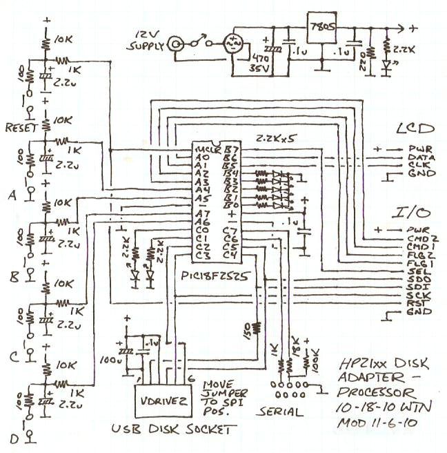
Here's the present hardware design...
Here is the present control firmware source
code
(v0.41) and docs. Here is the complete hpusb archive
(2.6mb, version 0.41 6/14/11) containing source code and hex files,
schematics and
documentation, HP minicomputer software, and a patched version of the
Great Cow Basic compiler. Here is the latest
firmware package (69KB, version 0.41 5/5/12), includes
just the
control firmware source, hex and docs.
Testing status...
Serial port and bootloader works (with my PC anyway).
LCD circuit works - disable PLL to run PIC at 8mhz when printing, use a
bit of delay after slowing clock.
SPI port and I/O chips work - using 8mhz SPI clock (32mhz
PIC clock) w/220 ohm series resistors.
VDRIVE bit-bang SPI works (180 ohm in series with data out), can access
via serial - disable HW SPI when using.
HP transfer stuff works - need to allow for line settling and depending
on HP-side software, timing can matter a lot.
Initial setup screens (polarity, LED functions), file/error display and
file attach screens seem to work.
Boots the initial "HPBOOT" binary using the papertape loader, VDOS and
UDOS work (mostly) without issues (*).
Tested with my 12V ground-true board (12554 "+16B DUP REG")
with the PIC running at
32mhz. Clean startup (**)
Tested with my 5V 12566 "microcircuit" board, ground-true with
ground-false control. Have to reset after powering HP (**).
Tested with my 12V ground-true punch board (12597 "+8B"), ran the
vintage HP assembler (w/ v0.4 firmware).
Note... the microcircuit board has a different pinout!
(*) 11/17/10 - previous 0.31 firmware had glitches when the disk
filled up, causing some VDRIVE commands to delay more than I was
waiting for. Also found bugs in the HP-side VDOS software. Should be
fixed now, but at the expense of speed... not unacceptably slow but
could be faster (v0.4 is much faster).
(**) 5/5/12 - the v0.41 firmware handles initial startup OK with a
microcircuit interface, says "WAITING FOR HP" until the minicomputer is
powered on (but power-cycling the HP might require resetting the USB
adapter). Regardless of the interface, power-cycling or resetting the
USB adapter after powering up or power-cycling the HP should always
bring up the adapter with the "HPBOOT" file attached (if it exists).
As of 5/5/12 I know of no significant operational issues with the
v0.41 firmware, at least with my setup, but depending on the interface
and cabling it might be necessary to play around with the command and
flag timing in the setup - mine is set to "Slow" for all. There are
some glitches in the hpusb.txt docs included with the main package - in
the "Firmware Usage" section in the paragraph starting with `For my
"+16B DUP REG" board', "control and flag lines both inverted" should
read "control and flag lines flipped" (that confused me when re-reading
the docs) and the paragraph starting with "The flag speed setting" is
not worded correctly, the choices are Slow (1.7uS) and Fast (1.2uS). In
the "Firmware disk commands" section, it omits the implied papertape
read command "000xxx", which places the next byte of the read file on
the HP input lines then clocks the flag line, although that's implied
in the PTRMODE code right before that, which simply clears the PTR/USB
interface output lines so that any PTR interface activity is
interpreted as a papertape read unless another disk command is sent.
Updated in the linked docs and hpusb_test.zip file, main package not
updated yet.
Hardware notes...
Switch and LED functions are determined by the firmware. The LED's on the punch port chip are intended for indicating manual file attachments if not using the LCD, or can be used for other blinky-light purposes. If the speed-hit is acceptable could be used to indicate data-flow. The main LED's are on PIC ports to speed up and simplify setting them. All inputs that need to be polled are on port A. The design is still a bit more complicated than I'd like, but considering that it can (theoretically) interface with both 12V and 5V boards and is reasonably properly designed (I think:-) I guess it's acceptable, at least it's not as many resistors. For connection to the HP I'm planning to use pre-fab 40-pin and 20-pin IDE-type cables wired to 48-pin edge card connectors, with the IDE socket wiring roughly lining up with the card edge pins. Not shielded, not really proper but should work fine if EMI output is ignored.
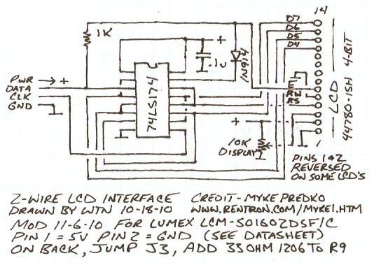
The LCD interface is a clever shift register circuit that's directly
supported by GC BASIC (PRINT etc), only 2 PIC pins are needed to drive
rather than the usual 6, freeing up the pins for additional status
LED's. The circuit was obtained from here, also explained here.
Others
report
the
circuit
works
fine
so
went
with
it
for
this
design,
although
if
needed
the
LCD
can
be
directly
attached
in
place
of
the
status
LED's.
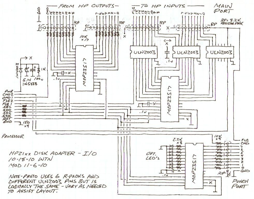
The entire I/O section is isolated from the main supply by a
blocking diode to prevent the HP minicomputer I/O lines from
backpowering the processor and VDRIVE when the adapter is not powered,
thus assuring proper reset should the unit require power-cycling. The
VDRIVE is particularly sensitive to this should a programming error
occur, supply voltage must drop to below 1V or less for a proper reset.
The I/O supply rests at about 4.3 volts, so small-value resistors are
used between the select, SPI clock and SPI data output lines to limit
current flow through the MCP23S17 input clamp diodes. Resistors are
also used in series with the SPI data input pin from both the I/O
section and the VDRIVE data output line to limit current in the event
of mis-programming.
Although targeted as a HP21xx disk adapter, the basic architecture
of this design can be reused for other control purposes, up to 80 more
I/O lines can be added by attaching more MCP23S17 chips. Although not
as compact as high-pin-count controllers, it's easier to program and
uses common inexpensive through-hole parts rather than exotic surface
mount stuff. Very perfable.
Here are a couple pictures of the prototype...
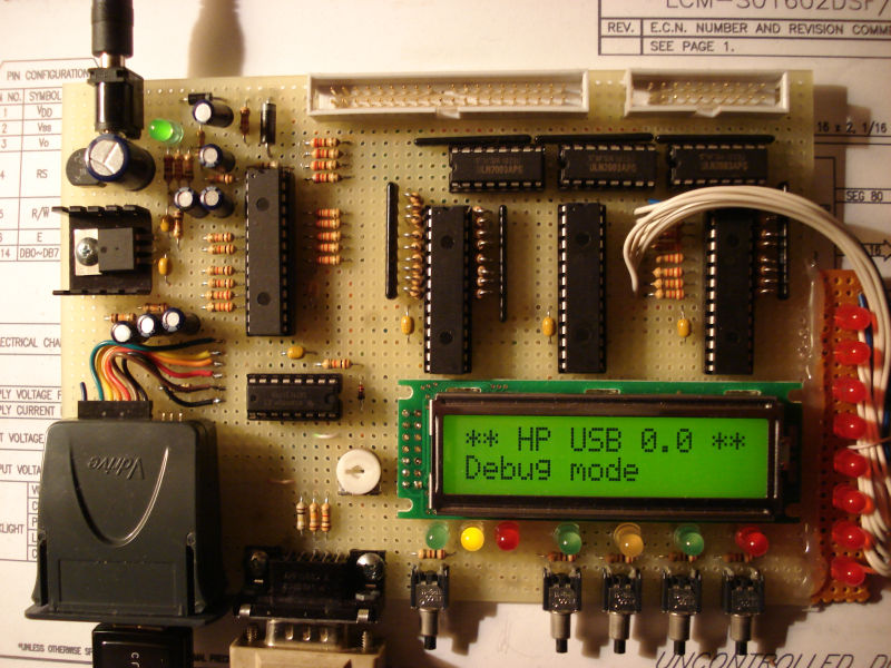
6.5" by 4.5" was a bit tight... wasn't planned quite as exactly as
it could have been, but close enough.
Ran out of room and had to put the extra port LED's on a piece of perf
glued to the side (for now).
Using a 33 ohm resistor for the Lumex LCM-S01602DSF/C backlight,
soldered on the back side of it.
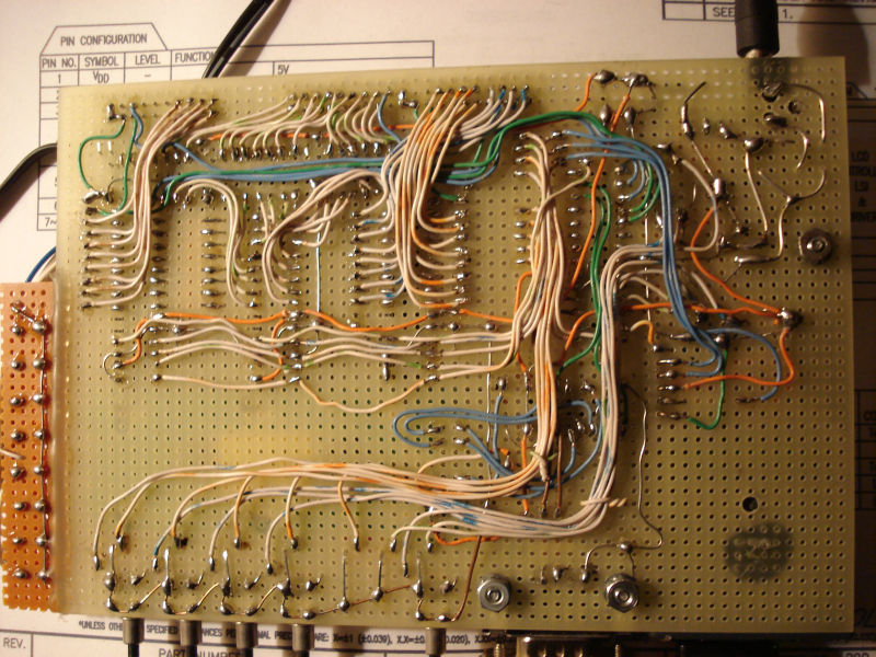
Lots of solid-core telephone wire! Some of the wires could have been
neatened up for the picture but the circuit doesn't care.
Here's the pinouts I'm using for the HP connectors...
Wiring side, or looking at the holes in the mating connectors
G = ground  C = HP command out  F = HP flag in

PUNCH connector...        MAIN connector...

         from HP outs      ----to HP ins----     ---from HP outs--
 G   F       7 5 3 1       0 2 4 6 8 101214F G    151311 9 7 5 3 1
 O O O O O O O O O O       O O O O O O O O O O   O O O O O O O O O
 O O O O O O O O O O       O O O O O O O O O O O O O O O O O O O O
 G G C       6 4 2 0       1 3 5 7 9 111315  G G C141210 8 6 4 2 0

"+16B DUP REG" HP 12554 12V interface connector pinout, looking at
the back of the machine or the wiring side of the connector...

 ------------- inputs ----------------------------------------------
 0  1  2  3  4  5  6  7  8  9 10 11 12 13 14 15                    F  G
 O  O  O  O  O  O  O  O  O  O  O  O  O  O  O  O  O  O  O  O  O  O  O  O
 O  O  O  O  O  O  O  O  O  O  O  O  O  O  O  O  O  O  O  O  O  O  O  O
 0  1  2  3  4  5  6  7  8  9 10 11 12 13 14 15                    C  G
 ------------- outputs ---------------------------------------------

The "microcircuit" 5 volt HP 12566 interface is different...

 ------------- inputs ----------------------------------------------
 0  1  2  3  4  5  6  7  8  9 10 11 12 13 14 15                 C  F  G
 O  O  O  O  O  O  O  O  O  O  O  O  O  O  O  O  O  O  O  O  O  O  O  O
 O  O  O  O  O  O  O  O  O  O  O  O  O  O  O  O  O  O  O  O  O  O  O  O
 0  1  2  3  4  5  6  7  8  9 10 11 12 13 14 15                 C  F  G
 ------------- outputs ---------------------------------------------
The plan (if I ever get around to it) is (or was) to use
pre-assembled 40-pin and 20-pin IDC ribbon cables
to connect the adapter to the 0.156" 48-pin edgecard connectors
(Digikey part number EDC305480-ND) that
plug into the I/O cards on the HP minicomputer. The main connector IDC
pinout is the same as I used for my 8052-based disk controller, which
has a salvaged disk cable for the connector thus the missing key pin.
For now I'm using that cable, moving the command wire depending on if
using the +16B or microcircuit I/O card (it was too short for my IDE
disk adapter anyway, so need to make a longer cable for that piece of
hardware). I'm not sure why the input/output bits on the 40-pin IDE
connector ended up mirrored, just the way the level shifters got wired
with no real planning but the layout does result in a 1-1
correspondence between bit and ribbon wire positions, and worked out OK
when wiring the adapter - just had to cross the high byte and low byte
wires from the HP out pins.
I ended up making a punch cable by cutting down an existing IDE
connector with attached ribbon which I attached to a length of
multi-conductor wire I found hanging around, fortunately for punch only
11 wires are needed. My "+8B" 12V ground-true punch board has a pinout
similar to the "+16B" board, only with 8 ins and 8 outs and some extra
lines for functions that don't seem to matter. HP input bit 5 is used
to indicate papertape fault, vintage software won't punch unless this
bit is logically low. For a ground-true board the input pins can be
left unconnected but for a ground-false board at least input bit 5 (and
possibly all of the inputs) need to be grounded so the software won't
think it is out of tape.
Note... beware of reusing IDE disk cables and especially don't use
the 80-wire variety - check for shorted lines.
HP Minicomputer Interfacing
Note... I'm not an expert at HP I/O, usually I just hack the code
until it does what it to do. The hardware was designed by referring to
the 12554A (+16B 12V) and 12566B (5V microcircuit) interface card
schematics. The rest is "as I understand it" (which might not always be
correct).
HP21xx minicomputer interface cards use separate lines for inputs
and outputs and use a simple command/flag handshaking method to
transfer data. To initiate a transfer the HP sets the command output
line, the peripheral reads and/or writes data, when done the peripheral
toggles the HP's flag input line which is normally kept false.
Typically (but not always?) as soon as the HP writes to a card (using
the OTA or OTB instruction) the outputs change, and changes to the
input lines can be read at anytime (using the LIA or LIB instruction),
but this behavior varies. The peripheral should only consider the data
to be valid after the command line moves from false to true, and should
not assume that changes to the HP's input lines can be read except when
it toggles the flag line. To ensure proper settling, a certain amount
of time should pass after receiving the command signal before reading
the data, and after setting the HP input lines before toggling the flag
line. The flag pulse needs to be wide enough to be recognized by the HP.
How much time that needs to be given depends on the cabling, line
impedance, capacitance and speed of the interface, usually 5-10
microseconds or so when reading is fine. In this project the
peripherals from the inputs are connected with 10K series resistors to
pins with 40pF capacitance, for a 12V board with a line impedance of
roughly 5K that's almost 1uS right there for 80% rise not considering
cable capacitance. Add in 300pF cable capacitance and it's over 3uS for
80% rise. The HP inputs aren't as bad since they have fairly small
pullup resistors, it's mainly the 12V HP outputs that are fairly hi-Z.
Reflections and ringing should also be considered but with the slow
high-Z 12V boards that's probably not a huge issue, and the time delay
to be compatible with 12V boards should be plenty fast enough for 5V
boards even if the data "wave" makes a few round trips before settling.
A 10uS read delay, 5uS write delay plus another 3uS for the flag toggle
still results in a raw transfer rate of over 50K transfers per second,
plenty fast enough for a vintage minicomputer. These are fairly
conservative figures, can probably be operated much faster.
According to the 12554A schematics, the 12V output and input lines
look like...
         12V                              12V
          |                                |
         10K                              1K
          |                                |           |
          *----> HP out          HP in >---*--2K--*--|<
          |                                       |   _|_
      --|<                                       10K
         _|_                                      |
                                                -12V
According to the 12566B schematics, the 5V output and input lines
look like... (4.5V may be 5V)
         4.5V                             4.5V
          |                                |
         1K                               316
          |                                |
   chip---*----> HP out          HP in >---*--chip
                                           |
                                          750
                                          _|_
The goal is to be compatible with both kinds of boards. To achive
this the adapter inputs and outputs look like...
                                          5V----*--|<|----.
                                                |         |
   From HP out >----*---10K----chip             `--8.2K---*-----> to HP in
                    |       (clamp diodes                 |
                   8.2K     to 5V and gnd)   chip---R---|<
                   _|_                                   _|_
The R, transistor and diode are built into the ULN2003 output
drivers. Note that when the clamp diode is wired 12V boards will dump a
fairly considerable current into the positive supply, on the order of
up to (12-5.5)/1K times 17 or about 110ma, that's why there's a big
honkin zener on the I/O supply with a blocking diode to prevent
backpowering the processor. For less sink don't connect the diode
clamps but the diodes may help absorb reflections. Judging from the 12V
HP input schematic anything over 3.5V or so will be read as high but if
there are issues can disconnect the clamps, should work OK without them
other than less-than-optimal matching on the high side (the 8052-based
circuit just uses plain open-collector transistors with no pullups or
anything and it works fine). The datasheet doesn't specify reverse
recovery time of the clamp diodes, I'm assuming it's reasonably fast.
When driving 5V boards the matching is rather poor but the low line
impedance (about 300 ohms) should quickly absorb any reflections and
the clamp diodes (assuming they're viable) will absorb any overshoot.
The 8.2K pullups could be lower in value, perhaps 2.2K but for now
trying it with all the resistor packs the same size - the 5V HP input
lines rest at about 3.1V and anything over 2.4V is high so should be OK
with no pullups at all.
For the adapter inputs, matching is about right for 12V boards
although the impedance remains fairly high, the 8.2K pulldowns sets the
max input voltage to about 5.5V so DC current through the 10K resistors
when the adapter is powered is almost none, and reasonably minimal when
the adapter is not powered (about 1/2 ma). Matching isn't great when
driving from 5V boards but the 8.2K loads don't pull the line down
significantly and the 1K driving impedance should absorb reflections
quickly enough, main delay will be from the 10K resistors to the 40pF
chip pin loads.
Firmware Design
The firmware programmed into the PIC chip needs to perform several
functions...
These are the main requirements... lots of tricky code! It is also
nice to be able to use the serial port to test the hardware, access the
VDRIVE prompt for file management, and use the serial port to open
named files (in the present implementation file names selected by the
switches are limited to a single letter).
Much of the code is open to interpretation and personal preference
(such as the debug menu, manual file attach screens and the serial
access menu) but some things need to follow strict protocols for
compatibility, especially when implementing the HP commands. Interface
cards vary widely so the machine-level transfers need to be able to
selectively invert the data and/or control signals as needed by a
particular interface board.
The input and output streams must be buffered for a couple reasons -
the main reason is internally the VDRIVE supports only one open file at
a time, it cannot support having a read file and a write file open at
the same time with independent file pointers as needed to support
papertape-based software and streaming methods. Because of this, it
would be excruciatingly slow to open, seek then close for every byte
read and written which can take hundreds of milliseconds - buffering is
a must. I used 1K-byte buffers in the present v1.21 firmware, there is
enough ram to use up to about 1.4K byte buffers but I didn't want to
take a chance of colliding with variables assigned by the compiler.
When a read file is opened, the firmware has to retrieve and save
the file size so end of file can be detected, set the file pointer to
0, and load the first part of the file into the read buffer with the
buffer pointer set to 0. For each byte read, if not the end of file the
next byte is retreived from the buffer, the buffer and file pointers
are incremented (setting the end of file flag if the file pointer is
equal to the saved file size), and if the buffer pointer increments
past the end of the read buffer (and not end of file), the read file is
opened, a seek to the current file position is performed, the read
buffer reloaded and the file closed (as far as the VDRIVE is
concerned), and the buffer pointer reset to 0.
When a write file is opened, the write buffer pointer is set to 0
and little else - no data is saved to the write file until/unless
byte(s) are written. Each byte written is stored in the write buffer
and the buffer pointer incremented. If the buffer pointer increments
past the end of the buffer, or after about one second of inactivity,
the write file is opened, bytes in the buffer are written to the end of
the file and the file closed, and the write buffer reset to zero. Note
that by default all writes append to the end of the file, to overwrite
an existing file a delete command must be sent to the VDRIVE. The
VDRIVE provides a means of detecting if a file exists so the software
or firmware can ask the user what to do.
The following commands from the HP need to be implemented...
120000 = 1010000000000000   read from VDRIVE
121bbb = 10100010bbbbbbbb   write to VDRIVE, byte in low 8 bits of command
122000 = 1010010000000000   sync VDRIVE (call before starting operations)
123000 = 1010011000000000   clear VDRIVE response buffer
130000 = 1011000000000000   open read file, follow by filename[cr]
131000 = 1011001000000000   read the next byte from an open read file
132000 = 1011010000000000   switches to paper-tape emulator mode
134000 = 1011100000000000   open write file, follow by filename[cr]
135bbb = 10111010bbbbbbbb   write to file, byte in low 8 bits of command
136000 = 1011110000000000   close write file (write remaining buffered bytes)
137000 = 1011111000000000   get error value
All commands except for open read file and open write file are
single-cycle - the HP places the command on its output lines and sets
the control line, the adapter responds to the command and if data is
requested outputs it the HP input lines, then briefly toggles the flag
line to tell the HP to proceed. Due to the glitch in the existing VDOS
and UDOS software, after toggling flag the firmware needs to wait about
12uS or so to give the HP time to process the data (command line
glitches and all) before monitoring for the next command. The open
commands require filename data, so when received they toggle flag, wait
for another command, get a byte from the HP out lines and store it in a
filename string, and repeat until a CR is received. Once the file has
been opened the flag line is toggled to tell the HP to proceed. The CR
is not stored in the filename string, if more than 12 filename
characters are sent, only the first 12 characters are saved. The VDRIVE
supports only 8.3-format filenames.
In addition to these commands, command 0 is treated as a read next
byte command, and any write to the punch port is treated as a write
byte to file command. The switch to papertape command tells the adapter
to behave as a papertape reader emulator until it receives another
command, the next command cycle (not changing the HP outputs) returns
the next byte from the read file.
The VDRIVE read and write commands permit direct access to the
VDRIVE for implementing dos commands from the HP (directory, delete,
change directory, prompt, etc). The read command returns bit 15 set if
the VDRIVE is busy. The write command waits until the byte is accepted
(at least until it times out). The sync command should be used before
any command sequence to make sure the VDRIVE output corresponds to
commands just given. The clear command empties the VDRIVE's output
buffer to ignore any remaining output so further output will correspond
to the next command.
The get error value command returns the global error variable, set by the various operations to indicate success, failure and other conditions. The following values are returned by the present firmware...
0 = no error occurred
1 = no disk - a USB drive is not inserted into the VDRIVE or it is not
FAT-formated
2 = command failed - usually this means file not found
3 = invalid filename - illegal characters in the filename
4 = file open - a buffered read or write occured while a VDRIVE file
was open
5 = disk full - no more room left on the USB drive
6 = input not open - a read was requested but a buffered read file was
not open
7 = output not open - a write was performed but a buffered write file
was not open
8 = end of file - no more bytes left in the read file
9 = zero size - attempt to open a directory or a zero-size file for
reading
255 = unknown, not sure what went wrong or an unrecognized command was
sent
Opens and close reset the error value to 0 if successful, reads and
writes set the error value if an error occurs but otherwise don't
change the current value. Other commands don't affect the error value.
The Bootloader
Normally a PIC chip has to be programmed using a programmer such as
the Pickit 2, but unless a circuit is designed for in-circuit
programming (more parts), the chip has to be removed from its socket
and placed in a programming socket. Not exactly convenient when it
might take hundreds of edit/compile/burn cycles to develop a complex
program. A bootloader solves this problem by permitting new application
code to be loaded through the serial port. I looked at a few existing
PIC18F bootloaders but none of them were suitable - they all required
using a special PC app, usually for Windows or requiring a bloated
framework to work under Linux, some required app changes to relocate,
required certain pins to select app or boot mode, or other had other
features that would likely interfere with usage in this project. So I
wrote my own bootloader using the Great Cow Basic compiler.
My bootloader has the following features... (v8 11/13/10)
Here is the gcboot source code and package with source, docs and hex file.
Up-to-date versions of Great
Cow Basic and GPUTILS
(or Microchip's
mpasm assembler) are required to modify, or use the patched compiler
included in the hpusb.zip project package. The hex file should work
as-is
if using a PIC18F2525 chip with a
non-interfaced serial port, and RB0 isn't grounded or connected to
another device output. Hook up something like this...
    O serial                    .----------------.
 O    port                      |            MCLR|--1K---*---10K--< +5V
 RX O--------1K-----------------|TX (C6)         |       |
 O                              |                |       `------*--100--.
 TX O----*---18K----------------|RX (C7)      Vcc|---*--< +5V   |       |
 O       |                      |                |   |         2.2u     O |
    O    `---100K---< +5V       |   PIC18F2525   |  0.1u       _|_        |--
 O                              |                |   |                  O |
    O----.     .--|<|---2.2K----|B0           Vss|---*                  |reset
        _|_   _|_ LED           `----------------'  _|_                _|_
The bootloader has to be initially programmed into the PIC
using a
conventional programmer such as the Pickit 2, but after that the serial
port can be
used to load application code without removing the PIC from the
circuit.
If needed the source can be edited and recompiled to configure for a
serial port connected
using an inverting MAX232-type interface, to specify the "run app" pin
and polarity, disable the LED or put it on another pin, change the baud
rate, chip config, etc. The code sets the "pll" bit to multiply the
clock rate by 4 (to 32mhz), if I specify 32 in the chip line it
confuses the compiler so the specified baud rate is divided by 4 and
all wait durations are multiplied by 4.
Here's a hex file sender script I threw together for my Ubuntu
system that supplies the needed line delays...
#!/bin/bash
serial=/dev/ttyS0
stty -F $serial 9600
if [ ! -e "$1" ]; then
 echo "Enter name of file to send..."
 read filename
else
 filename="$1"
fi
while read line
do
 echo $line > $serial
 sleep 0.05
done < "$filename"
echo "" > $serial
...not much to it, under Linux the serial port is just a virtual
file. It's harder to do something like this in Windows as usually a VxD
is required to access the serial port, but shouldn't require more than
a few dozen lines of VB code to pull it off. Or just use HyperTerminal,
set a line
delay of about 20mS and copy/paste the hex file into the terminal
window.
Here's the menu that's shown when the bootloader runs...
=== Terry's Bootloader ===  v8 11/13/10
Configuration = 32mhz MCLR LED=portb.0
Select...
P: Program (or just send)
M: Examine ram
V: Examine code
W: Wipe chip
X: Execute app
>
Option P is only needed if the hex file being uploaded contains
comments, otherwise can just send the hex file. As the chip is being
programmed it flashes the LED and prints a "." for each 32 word block
that's programmed. The M and V options are for examining ram and code,
these prompt for a ram block or starting address and dump 256 bytes in
hex format...
> m
HEX digit of block to dump: 1
0100: 06 EF 58 F0 FF FF FF FF 10 00 FF FF 27 D8 93 92
0110: 81 82 01 0E 04 6E 1A D8 81 92 01 0E 04 6E 16 D8
0120: 81 82 01 0E 04 6E 12 D8 00 EF 58 F0 03 00 FF D7
0130: 03 2A 04 0E 01 6E A5 0E 00 6E 00 2E FE D7 01 2E
0140: 00 00 00 00 00 00 00 00 00 00 00 00 00 00 00 00
0150: 00 00 00 00 00 00 00 00 00 00 00 00 00 00 00 00
0160: 00 00 00 00 00 00 00 00 00 00 00 00 00 00 00 00
0170: 00 00 00 00 00 00 00 00 00 00 00 00 00 00 00 00
0180: 00 00 00 00 00 00 00 00 00 00 00 00 00 00 00 00
0190: 00 00 00 00 00 00 00 00 00 00 00 00 00 00 00 00
01A0: 00 00 00 00 00 00 00 00 00 00 00 00 00 00 00 00
01B0: 00 00 00 00 00 00 00 00 00 00 00 00 00 00 00 00
01C0: 00 00 00 00 00 00 00 00 00 00 00 00 00 00 00 00
01D0: 00 00 00 00 00 00 00 00 00 00 00 00 00 00 00 00
01E0: 00 00 00 00 00 00 00 00 00 00 00 00 00 00 00 00
01F0: 00 00 00 00 00 00 00 00 00 00 00 00 00 00 00 00

Select...
P: Program (or just send)
M: Examine ram
V: Examine code
W: Wipe chip
X: Execute app
> v
HEX Address: 0000
0000: EF06 F058 FFFF FFFF 0010 FFFF D827 9293
0010: 8281 0E01 6E04 D81A 9281 0E01 6E04 D816
0020: 8281 0E01 6E04 D812 EF00 F058 0003 D7FF
0030: 2A03 0E04 6E01 0EA5 6E00 2E00 D7FE 2E01
0040: D7FA 2E02 D7F6 2E03 D7F4 0012 0EE8 6E02
0050: 0E03 6E03 DFED 2E04 D7F9 0012 0E70 12D3
0060: 6AE0 6AF8 90C2 9EC0 86C1 84C1 82C1 80C1
0070: 0E07 6EB4 6A80 6A81 6A82 6A84 0012 FFFF
0080: FFFF FFFF FFFF FFFF FFFF FFFF FFFF FFFF
0090: FFFF FFFF FFFF FFFF FFFF FFFF FFFF FFFF
00A0: FFFF FFFF FFFF FFFF FFFF FFFF FFFF FFFF
00B0: FFFF FFFF FFFF FFFF FFFF FFFF FFFF FFFF
00C0: FFFF FFFF FFFF FFFF FFFF FFFF FFFF FFFF
00D0: FFFF FFFF FFFF FFFF FFFF FFFF FFFF FFFF
00E0: FFFF FFFF FFFF FFFF FFFF FFFF FFFF FFFF
00F0: FFFF FFFF FFFF FFFF FFFF FFFF FFFF FFFF
This shows a small test program loaded into the app area, EF06 F058
is the jump to the bootloader, which is verified and added if not
present whenever the menu is shown as part of the init process. As the
hex file loads it automatically relocates the original GOTO instruction
(in this case EF06 F000) to locations BFF0-BFF3 so it can run the app.
Code memory is byte-addressed, instructions must start on an even
address with the LSB first (as can be seen in the ram dump of the flash
buffer at 0x100-0x13F), bytes in the code dump are swapped for human
consumption. The W option prompts to zero ram and/or erase code memory,
an uppercase Y must be typed to confirm each operation. The zero ram
function clears from 0x140 to 0xEFF so memory buffers etc viewed
without random garbage. The erase code function erases from 0004 to the
start of the bootloader, all but the initial jump. Normally it is not
necessary to erase code memory before loading hex files except to
determine what loads where. The X option jumps to location BFF0 to
execute the app's original initial GOTO instruction and run the
application. If the serial port is not connected (RX pulled high) the
bootloader immediately runs the application.
GC Basic's #option bootloader directive permits offsetting apps by a
specified amount, the non-destructive programming nature of the
bootloader makes it possible to have several independent apps loaded at
once. The first app can be a menu program that scans flash memory for
additional apps coded with a specific header, sort of like what PaulMon
does for 8052 systems. This would be really handy as it would permit
separating test and debug apps from the primary application, which the
menu would automatically run if no serial terminal is connected.
Haven't tried but it appears that an arbitrary jump can be performed by
doing a dummy call then replacing the TOS with the address to jump to,
then executing a return instruction. Probably other ways to jump around
at will but this seems to be the most obvious way to do it.
How the USB disk adapter processes
commands
HP21xx 16-bit parallel interfaces support bi-directional data
transfer, but there is only a single set of command and flag lines to
request and confirm transfers. To avoid confusing input and output
transfers (or both), the software running on the HP and whatever is
connected to the parallel interface must know what is expected for each
transfer. When the command line is pulsed true (whether high or low
depends on the particular kind of interface), the USB adapter firmware
looks at what is on the high bits of the HP output lines to determine
what to do. If it's a valid disk command then if it's something
requesting data then it loads the data onto the HP input lines then
pulses the flag line which tells the software running on the HP to load
and process the data that was sent back. If the command is sending data
from the HP to the adapter, then the firmware loads the data from the
lower HP output lines then pulses the flag line to tell the HP to
continue. The file open commands trigger additional transfers to pass
the filename, the extra transfers must complete or the interface will
get confused.
HP papertape-based software knows nothing of this and simply reads
from the PTR interface and writes to the PTP interface, so mechanisms
had to be devised to prevent
whatever happens to be on the PTR interface's output lines from being
interpreted as a command, and instead just send the next byte of the
read file (nothing needs to be done for PTP since its command line is
always treated as a write request). When the HP is powered on, unless
something writes something to the PTR interface, all output lines are
set to logical 0, so any command request with the upper output lines
clear is treated as a papertape read. One way for HP software to switch
to papertape mode after sending disk commands is to just clear the
output lines by doing CLA then OTA port (where port is the PTR/USB
device address). This mechanism covers some usage cases but it's still
possible for the interface to become confused, particularly when a read
file is attached using the USB adapter's controls or is reset.
To ensure that the HP's IBL mechanism and other papertape software will always work with no help from software running on the HP, when the interface is reset or a file is attached using the interface's controls, it looks at whatever happens to be on the upper HP output lines and saves it as a "ignore" command, so if the command line is pulsed and the output lines are still that value, then it assumes that a papertape read is being requested. Sending any other disk command (practically any disk command since the initial command should always be different than how the lines are left after a previous command sequence) kicks the adapter back into disk controller mode. A dedicated "PTR mode" command is provided which always engages this behavior, this might be easier for custom HP software to use as it's one less I/O instruction to have to patch when configuring the PTR/USB slot. The present VDOS software does not make use of the papertape-mode command and requires using CLA/OTA method before running vintage papertape software that requires a PTR attachment. A word for doing this is provided inthe docs, also used by the vintage.ipl package where it is run just before executing the assembler/compiler tools so that the attached read file will be read in papertape mode
HPUSB Firmware Docs
This was written for the v0.3 (11/13/10) firmware, changes for later
versions are in the update notes.
On startup or exit from the bootloader, the firmware quickly cycles
the data LED's once to indicate correct operation of the SPI buss. If a
serial terminal is connected (9600 baud) and the debug menu is enabled
in the stored setup, a debug menu is displayed that can be used to test
various hardware functions...
Debug menu
==========

Main polarity: inverted         Punch polarity: normal
Main control:  cmd/flag flipped Punch control:  same polarity
Main command:  clear            Punch command:  clear
Main data in:  1111111111111111 Punch data in:  00000000
A) VDRIVE prompt
B) Clock and redisplay
C) Flip main polarity
D) Flip punch polarity
E) Save polarity setup
F) Set main port output
G) Set data LEDs
H) Change main control setup
I) Change punch control setup
Esc) resume startup
Select:
After exiting the debug menu or on startup if the debug menu is
disabled, the firmware version and the text "D for setup" appear on the
LCD for about 1 second, to enter setup mode press switch D quickly and
hold it until "Setup polarity" appears on the LCD. Setup options are
main port polarity, punch port polarity, data LED functions and
enable/disable the initial debug menu. For each setup option, press the
A switch to change the data, press the B switch to confirm and continue
to the next item. The polarity options determine whether or not to
invert the data bits, if the punch port is not used select normal
polarity. The LED setup determines if data LED's respond
to commands,
read data and/or write data, all 8 combinations can be cycled by
pressing the A switch. The polarity of the control signals for the main
and punch port can
also be selected, normal if the same as the data lines, or command
and/or flag lines flipped. Setup can also be entered by pressing the D
switch if it
gets hung up waiting for the HP command lines to clear.
After exiting the setup, or on startup if D wasn't pressed, the
firmware checks the states of the main and punch command lines. If
either line is logically true then the LCD displays "Waiting on HP",
usually this means one of the port polarities is incorrect, or the HP
is not turned on with an inverted interface. If the HP is on while
displaying the waiting message, press Preset button on the HP, if that
doesn't do it then press D to reenter setup and correct the polarity.
When the command lines are logically clear the unit should briefly
display "Syncing VDRIVE" then display "SF HPBOOT" as it checks the disk
in the VDRIVE for a file named "HPBOOT", if found it is attached as the
read file, otherwise the unit starts up with no files attached and the
"error" LED lit The HPBOOT file should be an ABS-format binary
containing the default boot system, after a normal startup the HP's
bootloader can be operated to load the file - on a HP2113 this is
accomplished by selecting the S register, setting bits 11-6 to the disk
adapter interface slot address, then pressing Store then Preset IBL
Preset Run. LED's should flicker while loading, after a successful load
the LED's on the HP for bits 0-5 should be all lit to indicate a
successful load. Select the P register, Clear and set bit 1 for address
2, then press Store Preset Run to run the application. The exact
details vary somewhat for other HP21xx minicomputers, refer to the
documentation for the standard papertape load proceedure. Core machines
such as the HP2114 use a memory-resident bootloader with a hard-coded
slot address, which must match the slot for the I/O card connected to
the disk adapter.
Once set up and with no serial terminal attached, the above steps
all execute in a couple of seconds after powerup or a reset with no
interaction required, then the unit enters normal run mode. The LCD
displays the current file attachments following the "RF:" (read file)
and "WF:" (write file) labels. Normal "errors" such as EOF or a file
wasn't found are shown as numbers in the last column. These include 2
for command failed (usually file not found), 5 for disk full, 6 for
input file not open, 7 for output file not open, 8 for end of file and
9 for zero size (usually an attempt to open a directory as a file).
More serious errors preempt the normal LCD display and are spelled out,
these are "No disk" (code 1), "Bad filename" (code 2, invalid
characters in a filename), "IntFile open" (code 3, an internal file is
open on the VDRIVE, should never happen unless something abnormal
occurs like resetting the unit while writing data), and "Unknown error"
(code 255, something went wrong that I didn't bother parsing in the
firmware or the firmware couldn't make sense of). The fast way to clear
an error condition blocking the display is to press the reset button.
The status LED's are assigned as follows...
Port C bit 0 - "Ready" - lights when the unit is waiting for a disk
command
Port C bit 1 - "Busy" - lights when the unit is not monitoring for disk
commands
Port B bit 0 - "Serial" - lights when the serial port is active and
waiting for serial commands
Port B bit 1 - "Read open" - lights when a read file is open
Port B bit 2 - "Write open" - lights when a write file is open
Port B bit 3 - "Processing" - lights when processing a disk command
Port B bit 4 - "Error" - lights if the global error variable isn't zero
In run mode (when Ready is lit), the switches operate as follows...
Switch A - manual attach mode with the read file cleared (press A
then C to close read file)
Switch B - manual attach mode with the write file cleared (press B then
C to close write file)
Switch C - refresh the LCD to show an error condition
Switch D - run a serial file menu if a serial terminal is attached
In manual attach mode, press the A and B switches to select
single-letter files, or none. Press switch C to confirm the selection
and open/close the files if the filenames have been changed. Press
switch D to abandon the changes and return to run mode with the
previous file setup. If a newly selected write file exists after
confirming the selection, the LCD prints "File x exists" "C to
overwrite" where x = the letter file selected. Press the C switch to
delete the file to write new data, or any other with to append to the
file (which does not alter the file unless data is actually written).
When selecting files using manual attach mode, upon confirming
whatever is on the main input buss is recorded as an "ignore" value so
papertape mode will work correctly even if previous software set the
lines to something besides clear. File open commands and the sync
command are never ignored. Any data remaining in the write buffer is
written to disk upon selecting manual mode, and automatically written
after about a second in normal run mode, so it's not vital to close a
file after write operations.
The serial file menu permits attaching named files...
Serial file menu
================

Read file:    HPBOOT
Write file:   [not open]
Global error: 0
A) Open read file
B) Open write file
C) Close write file
D) Clear globalerror
E) VDRIVE prompt
Esc) Resume operation
Select:
Mostly self-explanitory. At the filename prompts press escape to
abandon without changing (such as after a typo, there is no backspace
editing in the current version, trying will result in error 3). Press
just enter to clear the filename, effectively closing the file.
Filenames are restricted to 8.3 "dos" format. Prompts to overwrite
existing write files.
The VDRIVE prompt is useful for checking the directory, deleting
files, changing to a new directory, making and deleting directories,
and listing text files, among things. Avoid using the file rename
option as it does not affect the long filename, a PC will continue to
see the original name which can lead to PC oddities like multiple files
with the same name, best to unplug the thumbdrive (but not while being
accessed!) and use a PC if a file has to be renamed. Common VDRIVE
commands include...
FWV - print VDRIVE firmware version (need at least 3.66 for reliable
operation)
DIR - list a disk directory
CD dirname - change to a directory one level lower
CD .. - go up one directory level
CD / - change to the root directory
DLF filename - delete a file
MKD dirname - make a new directory
DLD dirname - delete a directory (must be empty)
RD filename - list a file to the terminal - best used with text files
A reminder of the commands is printed when the prompt is started...
Select: E

VDRIVE prompt - send Esc at prompt to exit
Useful commands: FWV, DIR, RD file, DLF file, MKD dir, DLD dir, CD dir|..|/
D:\>
[ready]
Refer to the Vinculum Firmware User Manual (presently on this page)
for more information about the available commands. The command set
includes file opens, seek, block read/write and close operations for
creating more sophisticated disk applications if needed (such as a fast
copy that bypasses the streaming system), even raw sector read and
write commands for really advanced stuff. The VDRIVE only permits one
file to be open at a time so if using the file access commands always
close the file before reading and writing files with the streaming
system, it's OK if buffered stream files are "open", just don't read or
write to them, and allow at least a couple seconds to pass after the
last write for the automatic flush to occur.
This combination of hardware and software supports the full command
set used by the VDOS and UDOS operating systems, in addition to being a
full-featured papertape reader/punch emulator. Care needs to be taken
when mixing VDOS and papertape operations, in particular something
needs to be done to tell the adapter that further accesses are to be
treated as papertape reads unless a new command is sent. This can be
done by sending the papertape read command (octal 132000) to the
adapter from the HP software, or simply clearing the output lines by
executing CLA then OTA portaddress. This would be required to say use
HP-IPL/OS to semi-automate the running of vintage compiler tools.
Otherwise, restrict papertape reads to booting and manually selecting
files A-Z, which automatically sets up papertape mode.
A hex file for the current HPUSB firmware is in the hpusb.zip
project package. Due to its large size and extensive use of string
tables, modifying and recompiling the firmware requires using an
updated version of the Great Cow Basic compiler, included with the
package.
Update 11/14/10 - Version 0.31 includes two new LCD setup options
for command delay and flag speed. Previously I was using a fixed delay
of about 10uS before checking for the next command, but I ran into an
issue when using VDOS in conjunction with the TBG package - if an
interrupt to update the clock happened between sending a command and
fetching the data, it stretched the read (with its command line glitch)
to past the "ignore" time. To solve that I modified the firmware so the
amount of command delay was adjustable. [delay not required with the
updated VDOS/UDOS software]. The flag speed setting controls the width
of the flag
pulse, presently there is only a few hundred nanoseconds between the
two settings and both work with my machine. I was really chasing
another issue - with my microcircuit board, if the adapter is on and
the HP is powered, it sends a phantom command to the controller. The
adapter has to be reset before the HP's papertape loader will work -
which isn't a big deal (usually if I power-cycle the HP I have to reset
it anyway to attach the boot binary), but it would be nicer if
power-cycling the HP resulted in an automatic reset like it does when
using my 12V interface board.
Update 11/17/10 - I was getting strange behavior and "unknown"
errors when there were lots of files in a directory, so for version
0.32 I modified the VDRIVE code so most of it uses VDsendWait and
VDreceiveWait rather than the non-waiting versions to make sure nothing
is missed. Fixed the problem but at the expense of making it slower.
It's not too bad, takes about 15 seconds to load an app but it was
faster when it was processing dangerously.
Update 11/21/10 - was able to get it so that it boots a ~40KB ABS
file using the HP papertape loader in about 4 seconds even with
blinkylights. Speed with HP-IPL/OS and VDOS is improved but there it is
limited by the speed of interpreting code, still in the 15-20 second
range for saves and loads. Punch works but had to do a bit of rigging
to make the LED's blink with punch data. Rearranged the file attach
serial menu so option A is the dos prompt like in the debug menu, moved
everything else up a letter (also changed how raw mode works but I'll
have to write a PC app to test it). Although the new version 0.4
firmware seems to work perfectly, I did lots of surgery to get the
speed up and not sure I trust it yet, so linked in as a small update
download. Plus I'll probably do more to it... contemplating making the
VDRIVE "wait" factor an LCD setup option in case it's too fast for some
corner case I haven't run into yet [but didn't... haven't had any
problems with the present constants].
Update 11/23/10 - wasn't clearing read filename properly when
sending an empty string, fixed in v0.41. Some VDOS apps use this
feature and no issues encountered using the "fast" code, so updating
the main archive as well.
Development Stuff
10/20/10 - Today I should get parts... spent close to $300 at
Digikey but that includes about $75 for programming equipment (went for
the full PicKit 2 package and a pre-made 28-pin demo board for a
programming socket), and a few extra PICs and port chips to use for
other projects, but I still need to order the custom-made 40-pin and
20-pin ribbon-IDE cables (didn't want those holding up my order). About
$24 was for a pair of 48-pin edge connectors to make the HP cables and
about $14 for a couple pieces of DK's expensive perfboard. The 5
pushbutton switches were over $26 (ouch), about $16 for the LCD
display. About $25 for the VDRIVE. About $6 for LED's. About $11 for
power supply stuff including a 12V adapter (didn't get an actual power
switch). Chips, sockets, passives, etc for the actual circuitry was
about $35. With some junkbox scavaging I'm guessing the core parts
(chips, passives, VDRIVE, LCD and supply) could be obtained for around
$110 or so but as typical all the extra stuff adds up fast.
[...cleaning up the cruft...]
10/25/10 - got all the parts, haven't actually constructed anything
yet but getting close to diving in. I chose a 4.5" x 6.5" perfboard for
the project but it's tight with the LCD. All the major parts seem to
fit - VDRIVE, DB9 port, switches, LCD, supply parts, chip sockets, I/O
connectors - just got to make sure I leave enough room around each item
for the passives. No big hurry, better to make sure the arrangement is
right before I start wiring. Instead I took time to play around with
the PIC18F2525 chip on the 28-pin demo board with a serial port hacked
to it to make sure there are no unforseen issues that might alter the
design - so far the only needed changes to the 10-18-10 schematics are
a 100K pullup resistor needs to be added to the RX line so the
bootloader or other serial-using things will know if it's connected,
and the Lumex LCM-S01602DSF/C 2x16 LCD I got [Digikey # 67-1760] has a
slightly different
pinout and separate connections for the backlight, there's a jumper and
a place for a 1206 resistor on the back of the module to power it from
its supply pins. I'm still debating on whether or not to connect the 5V
clamp diodes on the ULN2003 chips... at the moment leaning towards not
connecting them - my existing 12V level shifters have nothing like that
and it works fine, and with the diodes connected it'll dump quite a bit
of current into the supply that has to be dissipated by the zener.
I wrote the bootloader so I could get a handle on using Great Cow
Basic before tackling the actual application code... it took a bit of
effort to figure out what I can do and what doesn't work. The only
major thing I ran into is it wouldn't execute past address
0x8000, making my 24KW PIC into a 16KW PIC. Fixed that problem by
installing a newer version of gputils and telling gcbasic to use it
instead of its internal assembler, now I've got a whopping 22KW (44KB)
for application code. There are definitely tricks to learn to make use
of gcbasic (as with any language) but so far so good... added the
bootloader section above.
10/27/10 - The fix for the 0x8000 issue was fairly trivial - in
assembly.bi after each of the comments to "Add high address?" (occurs
twice) in the next two lines change "FRA" to "(FRA - 32767)" then
recompile gcbasic using freebasic. Most of the time I prefer the
internal gcasm assembler over gpasm as it's faster and doesn't produce
a distracting warning about the case of the include file (it found it
so I don't need to know that). Although gpasm does produce
nicer-looking assembly list files... whatever works.
I'm wiring up the hardware... realized (fortunately before I got
to it) that I needed to add a few more resistors... the I/O subsection
can run at about 0.6 volts or so lower than the main supply so ideally
there should be a bit of resistance (220 ohms or so - might need to be
less) in series with the
I/O chip inputs to limit current flow should the protect diodes start
to conduct. In series with the I/O chip outputs back to the pic too to
protect from misprogramming. I'd probably
work fine without the extra resistors but it's more robust with them -
maybe - if it doesn't mess up the waves. Got the core CPU and LCD stuff
wired up... bootloader was intermittently broken and nothing on the
LCD. Bootloader problem was a bug (was referencing uninitialized memory
causing an intermittent address error, fixed), LCD worked fine once I
realized I had to InitLCD first (yay! that crazy circuit works!). The
chip needs to be slowed down to 8mhz before using LCD functions (Set
PLLEN off) but that was expected, being a one-way connection the code
can't check busy status so timing is fairly important. Last major "new"
thing to test is the hardware SPI functions...
10/28/10 - ...it mocks me... [gory debugging details removed but
what a trip] Looks like the compiler's SPI functions are not compatible
with this application, but once I figured out what to do writing my own
HW SPI code was easy, just a few lines of code. Got a simple LED chase
demo running on the SPI I/O chips, running the PIC at 32mhz with an
8mhz SPI clock with 220 ohm series resistors but for the design change
specifying 150 ohms, not only to limit possible current flow when
driving the lower-voltage I/O section but also to protect against
misprogramming. Similarly need a resistor between the VDRIVE's out pin
and the SDI pin in case that pin gets accidentally set to an output.
This was the last "new tech" thing to test, I've already tested the
VDRIVE and general disk adapter concepts in the context of the 8052
code so all that will be mostly just copying the existing algorithms,
adapting as needed. The idea is to not have to write much if any new
HP-side code (other than making sure the last command is cleared out
before attempting papertape reads on a file opened in VDOS). The VDRIVE
uses an odd 12-bit SPI format with the last bit being an ACK read,
probably will have to bit-bang some or all of it but I can just copy
the 8052 method. Barring unforseen bugs it looks like the rest of
implementing this will be grunt-work, still lots of stuff to wire and
code to write.
10/31/10 - everything is wired up except for the actual HP
connectors, that's today's project. Added another potential design
change - replace the 8.2K resistor packs pulling up the ULN2003
collectors with 2.2K for better compatibility with other applications.
As-is the outputs are unable to drive its own inputs but 8.2K is fine
if interfacing with an HP minicomputer, less backflow (but 2.2K would
be a better impedance match).
11/1/10 - Everything is wired up for the project,
starting on the actual coding [...bugs bugs fixes getting there...]
11/4/10 - The controller code is coming along... got just about all
of the low-level driver code for the VDRIVE and I/O chips in place, the
VDRIVE bit-bang SPI code works, I can log onto it using the serial port
and list directories, read files etc. The port expander drivers haven't
been fully tested yet but I can kick the chips into hardware address
mode and send patterns to the LED's connected to port B of the 3rd
chip, it appears that the VDRIVE and I/O chips can all coexist just
fine on the same buss. It is necessary to disable the hardware SPI
while bit-banging the VDRIVE. PIC bit sets and clears are very fast,
looks like I can bang the pins at an effective rate of about 2-3mhz
with a 32mhz clock rate. No problems with the 180 ohm resistor I added
in series with the VDRIVE's SPI output pin to protect from
misprogramming. If a serial port is attached then after reset it goes
to a VDRIVE prompt, theoretically files can be transferred between the
PC and VDRIVE with the appropriate software (but it's probably easier
to just plug the thumbdrive into the PC for that). I'll probably add
other functions to debug mode, possibly as way to attach files or
control other functions but for right now it's just a place to add
debugging code. If switch D is held on startup, after exiting debug
mode, or while waiting for the HP command lines to clear, it displays
prompts on the LCD to alter the main and punch port polarities (normal
or inverted), saves/restores the settings to and from eeprom. Got the
stream stuff up to the point of opening the initial boot file and
filling the buffer with the first part of the file, if it exists,
otherwise starts with no file attachments. Using 1K byte read and write
buffers for now. HP machine transfer drivers have not been tested yet,
still have to write most of the streaming and HP command interpretation
stuff before it can actually be a USB disk adapter for a HP
minicomputer.
Not all the time was spent writing code.. also having to learn how
to use the GC Basic compiler and figure out why code that looks correct
doesn't work. Originally I was trying to specify in, out and optional
for sub parameters which caused bizarre behavior - eventually figured
out it was generating invalid assembly, recoded to use simple sub parms
and learned to always use the gpasm assembler (from gputils) to weed
out stuff like that. In one case the compiler generated an out-of-range
RCALL, once was enough for me to edit gcbasic.bas, find the
OptimiseCalls subroutine, lower the 1024 range limit to 600 to be safe
(with 22KW available and so far only using about 3KW, aggressive
optimization is not a concern). Fortunately GC Basic is GPL-licenced
open source, making it possible to fix such things myself and
distribute the fixes as needed, which is a major plus. So onward...
11/6/10 - First boot! sort of. Not right though - loader shows
checksum error, hits EOF of boot file (supposed to terminate before
that) and when loading a multi-segment binary the last part didn't
completely load. Got lots of debugging to do, also need to make sure
all the hardware is working like it should. This was with the unit
connected to a 12V inverted interface card, haven't tested with the 5V
microcircuit interface yet. It's gotta be close, even though there were
bugs I was able to run the boot program (a VDOS system), enter VDIR and
it displayed the thumbdrive directory with no corruption (then locked
up:-), so back and forth communications is working to a degree. I'm
being pretty aggressive with multitasking the HP and controller, so
it's possible I'm not waiting long enough for line settling and getting
a false command or something... the lines are fairly high Z, there's a
law written somewhere that if all lines in a cable except for one
change state, that line will also change. Might need more delay before
I look for the next command.
11/7/10 - Appears to be working OK now - checksum error was because
I was checking for errors after filling the read buffer, and the VDRIVE
returns an error code (at the moment don't know what) if there is less
than a block's worth of data left in the file (for now just commented
out the error check). Major debugging session - I misunderstood how the
existing 8052 firmware and VDOS software worked, turns out read data is
returned in the same transfer, not a separate transfer. Once I figured
that out things started to work, but timing is still important because
the existing VDOS software aparently sets then resets the command line
again even though the transfer is already been flagged - that's a
legacy bug that the old 8052 adapter was too slow to notice. Could
probably just be a LIA. A side effect of this is there has to be enough
delay between completing a command and polling for the next command to
ignore the glitch. Hmm... I probably should fix that in the VDOS/UDOS
software but also need to be careful to not break it with the original
firmware [safer to leave it alone]. The lesson here seems to be just
because something works,
doesn't mean it doesn't have a bug. In the process of figuring how the
existing software actually worked and fixing other bugs I probably
complicated my present PIC firmware quite a bit, recoded all compound
bit conditions and string comparisons to explicitly test the raw bits
and array elements, even did string(0) = 0 instead of string = "" - was
getting weird issues that turned out to be just my bugs but I'm going
for a functional disk controller first, once happy that the algorithms
are correct then I can stress the compiler some more.
[bla bla bla deleted]
11/8/10 - Got version 0.2 now with many interface enhancements,
including file overwrite prompts, hardware testing options and a file
attach menu using a serial terminal. Added extra logic to help it
behave better when mixing VDOS and papertape modes, the manual file
select locks out whatever is on the high buss bits so if it remains on
the buss it will be ignored. Mostly - certain critical disk commands
are never ignored and immediately restore full disk adapter operation.
The program is getting fat! and stressing the compiler even more - had
to reduce its scan range for relative jumpts to 50. The issue is string
tables - it doesn't count them when calculating jump distances. There's
got to be a more efficient fix than my get-over hack.
11/9/10 - Hugh (the author of gcbasic) fixed the issue and sent me an updated gcbasic.bas file, the controller firmware compiles fine now without having to lose branch optimisations. Code size wasn't an issue for me (I'm using only a fraction of the available program space), was more worried about disturbing the timing in the various waits needed for proper operation. I spend a bit of time today running my HP2113 minicomputer with the USB disk adapter, seems to work OK with VDOS, UDOS and as a papertape emulator, at least with my 12V "+16B DUP REG" inverted interface board. No luck yet getting it to work with my 5V microcircuit board (which has a slightly different pinout, command is on a different pin). [...] duh, I had it wired wrong, the control line on a 12V 12554 board is the flag line on a 5V 12566 board... no wonder it didn't work!
For now I need to package and document what I have, at least for 12V
boards it seems to be working fine.
11/10/10 - The hpusb.zip "complete" archive is posted... it's fat -
4 megabytes mostly consumed by the patched compiler, complete with
binaries for Linux and Windows. I threw it all together fairly quickly
as I've got other stuff to do, so forgive an occasional typo. Code-wise
I'm sure there are bugs to fix but it seems to be working essentially
perfectly, at least the aspects I've tested. There's still more I'd
like to do... redraw the schematics to better reflect the prototype,
and make a Digikey parts list [got the parts list added in, updated
schematics will have to wait].
11/11/10 - Rearranged sections on this web page to make better
sense, edited as needed and totally rewrote the firmware design
section. I still have a few more tests to do (microcircuit
compatibility, punch) but everything I have tested works fine - so
linking it in.
11/13/10 - [rough notes removed] Got it to work with my microcircuit
interface... but it took some code. Besides the obvious wiring issue,
my microcircuit card inverts the data (which I knew) but the command
and flag lines are normal polarity. The 0.2 firmware couldn't handle
that and had several places in the code where it checked the command
lines directly for various reasons, all these had to be replaced with
calls to subroutines so that logic could be added to account for
"flipped" command polarity. The flag toggles already had subroutines, a
bit easier there. On my card both control lines are flipped in respect
to data polarity, but I made it so that both the command and the flag
lines could be individually flipped, for both the main and punch ports.
I implemented it so that the primary main and punch polarity invert or
not invert all lines, including control lines, and added additional
setup options to flip the command and/or flag lines if not the same
polarity. This is slightly confusing but should result in faster setup
- the default with a fresh PIC is to invert data lines with the control
lines also inverted (not flipped) so with a typical ground-true HP
interface nothing needs to be done, and if not using the punch then
only one option has to be changed - set the punch to normal polarity
(which also sets the control lines to normal polarity). The control
setup options only have to be changed if the control line polarity
isn't the same as the data polarity. The other way to do it would have
been to set the data polarity and control polarities independent of one
another, but then more setup would be needed to handle what I suspect
is the two most common cases - everything inverted and everything not
inverted - so did it the way I did. Whatever works.
While at it did other fairly minor stuff, like enabling PTR mode on
bootup and when attaching files via the serial port - PTR mode doesn't
preclude using disk commands, it just makes the interface ignore
whatever the last command was so if it remains on the buss it won't
trigger false commands. File open and sync commands are never ignored,
almost always with VDOS-type code these are not the last commands sent
(usually it is a get error or a read byte command) but some care will
still be needed when using VDOS to operate vintage code. The most
bullet-proof method is to execute CLA, OTA port to clear the HP output
buss before using papertape software (or send the PTR command 132000),
or don't use VDOS at all when running vintage code. Control code now
v0.3 until I find something else that needs to be done to it. Another
little bug - the v7 gcboot bootloader change added a Set PLLEN off
instruction when running the app so it'd default to 8mhz unless the app
kicks it back to 32mhz (GC Basic doesn't default this bit so timing
would be off for other apps), but that had a side effect of garbling
the "X" echo when running the app. So added a Wait to let the serial
out buffer fully clear before downshifting, now v8.
11/14/10 - ran into a couple of issues - the VDRIVE and/or VDOS (not
sure which) gets flaky when streaming files within subdirectories,
VCOPY would not work when I was 2 levels deep, worked fine in the root.
Other VDOS commands seemed OK, not sure what was going on. Other issue
was the amount of command delay was still not enough to avoid
occasional glitches when interrupts/TBG going. Added new setup options
for command delay and also flag time, which can be tricky at times.
When VDOS is patched to fix the extra STC SFS JMP instructions before
LIA, it works with no extra command delay. Still might need to adjust
the startup flag states, previous versions actually powered up flags
true (supposed to be false I thought) but wondering if that might be
needed - with the flags clear on startup, giving just a kick pulse, the
disk adapter needs to be reset if powered when the HP is turned on. At
least with a microcircuit, haven't retested yet with my 12V board.
Still might need to mess with this part, it used to not require a
reset. Hmm... basically it's working but this is the first time I've
used my microcircuit board for disk, might have a few effects to
investigate.
11/17/10 - fixed (I hope) - found cases in both the firmware and
VDOS where it was not waiting long enough for VDRIVE commands to
respond when it had to search through a bunch of files... especially
with the VDRIVE's DIR command... I thought that when it output the
first CR then the rest of the data would be ready - wrong. Have to wait
for all the bytes to be returned. The 0.32 firmware is slower, but
steady. Now that the main issues seem to be cured I can work on
optimising the
speed (hopefully without breaking it) - do something with VDclear,
VDsend[Wait] and VDreceive[Wait], increase the buffer sizes and make
sure the FillReadBuffer and FlushWriteBuffer subs are as fast as
possible. But no faster.
11/21/10 - working on version 0.4 with faster VDRIVE subs... boots
really fast but initial version broke
some VDOS words, slowed down just that part down without
slowing it down for everything else... fixed (maybe, appears to work
but haven't done margin testing yet). Tried punch... bits 1,3,5 are
always set in the resulting file. Not the hardware, manually making
pins high causes the right data to be read. Very consistent, like it's
something in the card - oh crud - the IDE disk connector I scarfed and
cut down has pins for bits 1, 3, 5 shorted internally to the pins I was
using for ground - well that explains that! 40-pin IDE connectors with
80-wire ribbons cannot be reused for other stuff. Another thing to look
out
for is the "tape full" line, HP input bit 5, for some SW/hardware this
may need
setting to something... for my "+8B" ground-true punch board I can
leave it open. Punch works now, used HP-IPL/OS with VDOS (with an added
PT12 word containing CLA, OTA 12) to run the vintage EXTASMB assembler
to assemble the HP-IPL/OS kernel source. Took about 20 minutes to run
the assembler but it worked, gives an impression of what it was like to
develop software in the late '60's - besides taking what seems like
forever (at least it prints the listing as it outputs code), the
vintage HP papertape dev tools did not have command lines or any kind
of terminal interaction - the user has to press switches on the front
panel to run the stuff, and one wrong press usually means starting
over.
My next hack will probably make a set of VDOS words that semi-automate
using EXTASMB ALGOL FORTRAN and BCS, what can't be automated can be
instructions printed to the terminal explaining exactly what to do.
There is already a text editor of sorts (AEDIT) that can at least
handle small programs, theoretically with this little USB disk adapter
gizmo I can edit, compile, link and run code using vintage tools on
real hardware, something previously I could only do under simulation.
If the lack of authenticity of VDOS matters (they didn't have USB
adapters with FAT32 back then), then it can all be accomplished using
just the switches and single-letter filenames representing papertapes.
What would Really Be Cool (but difficult) is if instead of restricting
it to selecting files to A-Z, make it so that it can cycle through all
the files in the current directory, changing directories if a directory
selected - that may be easy on a PC but this is a PIC with about 3KB
free ram, a 2-line LCD and 4 switches. Will work on the vintage
compiler VDOS words first, lots easier, it selects the filenames so
mostly eliminates having to press anything on the disk adapter except
for having to reboot the system after messing up.
11/23/10 - The "fast" firmware seems to work well, plus found a bug
in the part that parses a filename from the HP (fails if empty) so
upgraded all copies to version 0.41. The vintage compilers work, the vintage.ipl package supplies VDOS words
that permit assembling and/or compiling ASMB, FORTRAN and ALGOL code
and linking the modules into an ABS file. Here's a log file showing the compilation
of a Reversi game I made and an antique chess program. Quite archaic
compared to PC software development but in the HP minicomputer hobby
world this is a pretty big deal due to the typical lack of peripherals
required to complete such things... previously (before this project) I
could only use the vintage dev
tools under simulation. The vintage tools require configuring...
SIO.ABS needs to be slot-patched to match the system using sioutil.ipl
and the BCS linker has
to
be
prepared.
11/25/10 - Updated the main archive... the patched GCB compiler is
now a tar.gz file, saving more than a meg and a half in the archive and
about 8 megs when unzipped. Fixed Peek/Poke (the firmware uses custom
peek/poke code so isn't affected). Included the vintage.ipl package and
a text file explaining how to use HP-IPL/OS, VDOS and the USB disk
adapter to configure vintage compiler tools and use them to compile
programs... it's a tedious process, might still need doc or ipl fixes
(found gruesome bugs in the original version - wasn't clearing alt mem
before loading BCS so sometimes it worked, sometimes it didn't.. should
be fixed now). Definitely experimental, but loads of fun. Just getting
it to work is half the fun so if bugs remain consider that a bonus (ha).
6/14/11 - Hardware-wise it all seems to work OK, holding at firmware
v0.41. I had a case where it started doing weird stuff but reached in
the back of my HP2113 and wiggled the cards, problem went away (oxide
can have drastic effects). I ran into a few HP-IPL/OS bugs - VLOAD
(actually the DMS package's alt/main memory swapper/runner) wasn't
clearing the A/B registers when running binaries, most apps don't care
but made the BCS linker think it was running from another OS causing it
to hang when done, and the UFWORD that uses the VDRIVE's DIR command to
get filesize was failing when there were lots of files on the disk,
which makes it take a bit of time before it sends the size information
so the app needs to wait for it. Fixed these and a couple other minor
issues with new v1.64 VDOS builds and packages, updated the hpusb.zip
archive.
5/3/12 - I modified UDOS and VDOS to work with 32KW machines...
UDOS32 now has extra commands for binary load, binary load and run, and
attach write file, in addition to the previous save memory, attach read
file, VDRIVE prompt and run from 2 commands. VDOS32 is mostly the same
as the regular 64KW version of VDOS, except UDOS32 is built-in and the
VLOAD command uses code from UDOS to load binaries, overwriting the
VDOS system. UDOS remains in memory to provide a way to reload the
system or load another binary. Using vintage software that requires an
input file attachment cannot be automated (can't use ABSLOAD to load a
binary into alt memory, attach, then execute), instead VDOS has to be
used to prepare the files (doubling asm source, appending together
objects etc), then UDOS has to be used to run to load the binary or
binaries, make the attachments, set the switch settings, then halt the
machine to run from whatever address the tool needs to be run from. A
bit more involved than "APP.ASM" "APP.ABS" ASMB but at least it can be
made to work. The new code is in the udos32.zip
file.
5/5/12 - I noticed a few glitches in the hpusb.txt docs included
with the firmware code... added a note about it under the schematics in
the "Testing status..." section. Updated in the hpusb_test.zip file and
the linked docs, main package not updated yet. I'm working on a new
package, right now not much has changed besides including the UDOS32
stuff but considering including a binary directory containing stock and
modified vintage and vintage-like HP apps to use with the USB disk
adapter - for now all that stuff is available in the HP-IPL/OS testing archive.
One aspect of the project that might be lost in the noise is an
overview of how HP bi-directional interfaces work and how the USB disk
adapter is able to support disk commands while remaining compatible
with existing papertape-based software. So I added a section explaining
how the adapter processes commands and the mechanisms required to mix
adapter-specific software (like VDOS) and vintage papertape software.