Note... This page is under construction...
Background
The original PB2 (and PB2-mini) robots had inputs for 2 feelers, 2
photocells and a 1381 voltage sensor, and 4 outputs for driving 2
motors via a pair of H-bridge chips. An extra output drove a status
LED.
The robot was programmed using a PC's parallel port and custom "dos"
software written in QBasic. My PB2-mini robot still works fine after
about 7 years, however during that time operating systems have evolved
to prevent casual access to the parallel port so the only practical way
I can program a PIC16LF84 (PB2's processor) on my "new" machine is to
boot from a Win95/Dos floppy disk. To make this bearable I set up a
graphical Dos environment using WinDos (now Spectra). Other available
options are use commercial Windows-based software and hardware such as
EPIC, or fire up my old Win95 computer. I run Linux these days so these
options are as inconvenient as booting from a floppy. At least with the
floppy approach I was able to set up and operate my Dos
robot-programming environment under Linux using DosEmu, at least for
everything except for actually burning or extracting the robot's code.
Fortunately the 18-pin PIC has not stood still, the newer PIC16LF88
chip has roughly 4 times the capacity of the
'84 and runs twice as fast using an internal clock which
doesn't consume pins, permitting more I/O capability. Most importantly,
the '88 is able to read and write its own program memory using
software, making it possible to load it with a "monitor" program that
permits programming using a serial port and standard terminal software,
eliminating the hassles of port access and custom software once the
monitor has been programmed into the chip.
The extra pins can be used to drive IR LED's to allow using the
photocells for simple obstacle detection, and to provide a sensor power
output to allow using phototransistors and the '88's analog inputs to
directly read light levels, providing more resolution than the
photodiodes and capacitors used on the original PB2. Traditionally IR
obstacle detection was done using tuned IR receiver modules, however
these require more inputs and the LED(s) must be flashed at a precise
rate, complicating the software. Recently on the internet I've noticed
a few robots using "direct observance", or comparing light
readings between the LED(s) on and off using the existing light-sensing
photocells and triggering an
obstacle detection hit if reflected IR is observed. Kind of like if we
turned on a flashlight and saw something directly rather than having to
rely on a bit from some gadget. This method only
requires outputs for the IR LED's and makes it possible to implement at
least crude obstacle detection in a tiny robot with a minimum of extra
parts. Direct observance has its issues, such as sensitivity to
flickering lights or moving objects, but those aren't really flaws,
just what the sense picks up. It's up to the learning machine (or
programmer) to make use of it for what it is. All simple IR reflection
senses including receiver modules are subject to great variability
anyway due to drastically varying amounts of reflection, the only way
to get around that is use an angle-sensitive sensor, beyond the scope
of this sort of tiny robot. The other issue is anything that disturbs
the power supply also typically disturbs the perceived light level,
which if too great and in the wrong direction can generate false
obstacle hits. Careful engineering can minimize or at least make the
errors consistant enough to null in software by responding only when an
increase exceeds a threshold.
The Original PB2 Robot Design
A miniature version of this was produced
which used a 0.1uF rather
than a 2.2uF capacitor on the supply rails, omitted the (visible) LED
and resistor, used 470 ohm rather than 1K resistors between the PIC and
the motor drivers for stronger drive, and omitted the zener diode which
in retrospec was not a good idea, especially when I started playing
around with code that "watches" rather than immediately activates, then
used a 9V battery via a several-hundred ohm series resistor to power.
The super-caps didn't like that one bit but seem to have recovered
after resting a few days. 47uF across a
0.1uF for the local supply capacitor is probably better than a single
2.2uF. 470 ohms is a better value for the resistors from the PIC to the
motor drivers, greater saturation so less drive has to be applied.
PB2 Resources...
The original PB2 page
The "self-wiring bicores" page
A collection of PB2 programs (hex and source)
The SIMPLE compiler (needed to recompile sim
sources)
QBasic/Dos PIC-programming software (pure Dos
or Win9x only)
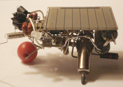
Modifications to my PB2-mini robot
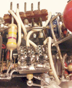
To test direct observance techiques I made a few changes to my
PB2-mini robot. First off I added a small board containing two BCX70
transistors, four 82K resistors dividing the outputs of RB6 and RB7
(the programming pins) and applying to the transistor bases, and two
470 ohm resistors from the collectors to drive two IR LED's, which were
mounted on the robot's head just above the photocells with the anodes
connected to the positive supply. RB6 drives the right LED (when high),
RB7 drives the left LED. Using this setup I found LED's that the SFH205
photodiodes could "see" and got the robot to display useful but highly
variable obstacle avoidance behaviors. Added the LED and 470 ohm
resistor for debugging but then I could really see the variability and
soon noticed it not working correctly.. at first I suspected quantum
interference (:-) but soon realized I was cooking the caps from
overvoltage, added a 5.1V zener diode across the rails and eventually a
47uF as well to help stabilize the supply for more accurate readings
and less dependence on the super-caps. Things are still highly
variable, but no more so than trying to use receiver modules at close
range.
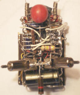
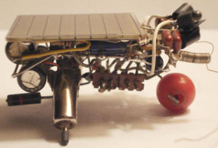
The IR LED's are heatshrinked and the back ends painted black to
avoid radiating IR into the photocells and causing false hits. Pieces
of tape provide additional blockage. It is important that the LED's
radiate IR at about the same wavelength as the photodiodes. The first
set I tried didn't work at all, a second set of smaller high-brightness
IR LED's produced about a 3-5% difference in light level from the
photodiodes between on and off. This is using simple
capacitor/photodiode inputs that return a value of 0-127 based on the
inverse of how long it takes for the photodiode to charge the capacitor
enough to register high, typically differences of 2 to 5 counts are
useful detection thresholds.
Presently the robot is running code
for a variation of the self-wiring bicores
program,
with IR obstacle hits recorded as feeler hits but not scoring IR hits
as "bad". To avoid mighty odd behavior run something like clearram.obj
from pb2progs.zip first to clear the in-memory wiring and weights.
Embracing variability, the program can decide to ignore
feeler (and IR) hits or do something besides backing up, so to make it
possible to adjust the obstacle detection system it flashes the status
LED when it detects an obstacle using IR reflection. This program uses
a differential method, it turns on
one IR LED, reads and saves both photocells, turns that LED off and
turns on the other IR LED, reads the photocells again, turns off the IR
LED and registers an IR obstacle hit for a side that shows an increase
in light level when the IR LED was on. This keeps current drain
constant while reading the light levels to avoid error, but tends to
cause a forward blind spot if it reflects IR equally back to both
photocells. The program is scaled to be most effective in relatively
dim light, constants towards the front adjust the light range and
detection thresholds. Ideally the light range constant (phrange) would
be a variable and under program control so that it could be reduced or
increased as needed, but with almost no free program memory adding
something like that to this particular program would be tricky.
These PB2 mods were mainly for testing ideas to convince myself that
direct observance of IR reflections to detect obstacles could be made
to work, in advance of making a new tiny robot platform. If it works
with crude "psuedoanalog" photodiode/capacitor inputs I'm pretty sure
it'll work fine with a real analog-digital converter with at least 3
bits better resolution. There are still problems to solve, but for the
most part the same problems that exist when using receiver modules,
like variable IR LED drive depending on supply voltage, and getting it
just right so it works even when the robot is placed on a white paper
floor. While it is tempting to try to gain "perfect" obstacle
detection, doing so would require special sensors that likely won't
make good general light sensors, and more pins than can be obtained
from an 18 pin PIC without adding extra circuitry. Better to accept
that IR reflectivity variability is a given and solve the "problem"
using adaptive software and let the robot figure it out for itself.
A new PicBot circuit
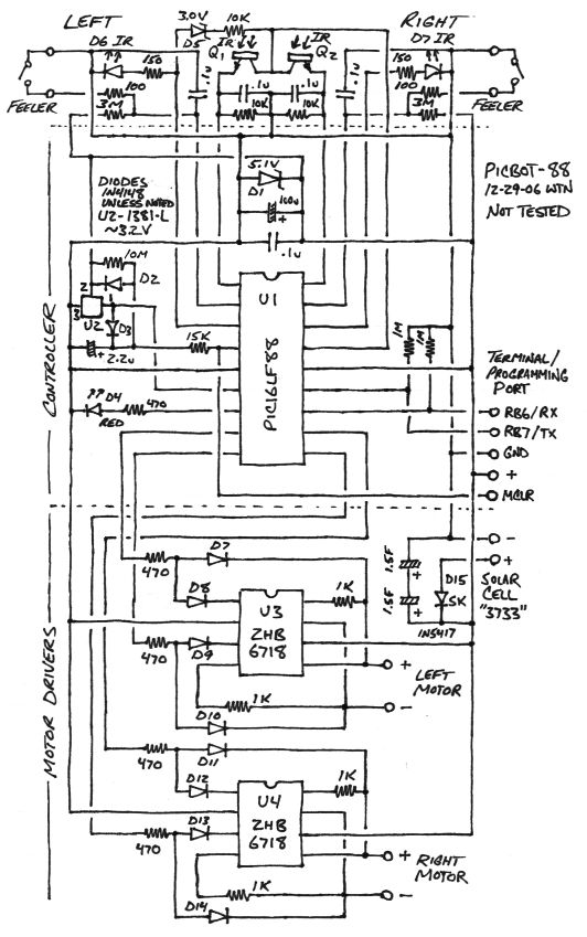
This circuit is almost as simple as the original PB2, but provides
IR obstacle detection and has four times the memory, enough to include
a serial port monitor in the top 1KW and still leave 3KW for program
code. The left IR LED output doubles as an input for reading the supply
voltage using a zener diode and series resistor, good for a range of
about 3 to 4.4 volts depending on the forward voltage of the IR LED and
the zener voltage. Better than nothing, should be enough to be able to
ramp the IR drive up and down in response to supply voltage for more
consistent IR performance. IR phototransistors are used for "eyes" to
provide a lower impedance and more accurate analog-digital conversion,
to avoid draining power when resting the phototransistors (and
voltage-measuring circuit) are powered only when a PIC pin is high.
Capacitors on the photocell inputs permit variable IR drive using PWM
(pulse-width modulation) without having to worry about keeping the
LED's on (particularly partially on) while reading the photocell
inputs, just read it before the voltage change decays. Component values
are guesses but should be in the ballpark... this circuit has not been
tested but looks good (and simple) enough to go for.
First step is to get hardware to play with then the real fun begins,
the software where the deficiencies of simple hardware have to be made
up for. Since it's software it can be whatever works but likely I'll
want to program it so the top 256 to 512 words contain critical serial
input, hex-file decoding and flashing software, the rest of the top 1KW
for the monitor menus, functions etc so that most of the monitor can be
altered via the serial port without having to attach a "real" PIC
programmer. The next-to-top 1KW would contain subroutines for driving
the motors, reading and writing the 256 byte internal eeprom, reading
the senses including light levels, feeler states, supply voltage and
obstacle detection. There will probably be enough room there to include
things like generic bicore and neural network engines that can be
accessed by the user-programmed code located in the lower 2KW. The
first few instruction locations are
always a jump to the monitor so it can determine if a serial terminal
is connected, if not it executes the first few instructions of the user
code then continues on as if the monitor didn't exist. No
changes need to be made to the user code to call (or forget to call)
the monitor, it just doesn't program the first few locations (leaving
the monitor jump intact) and instead puts the first part of the user
code somewhere else.
To Be Continued...