By Terry Newton
On this page I hope to provide more details than I usually provide for those who wish to construct their own PIC-bot, realising that people actually try to make this stuff. Traditionally, my 'bot pages are for documenting the essentials, not in the kind of detail needed to make as if it were a kit. I document my projects bugs and all, but the simple PIC-bot needed to be worked out. The original 5x platform was too complicated and required too much equipment to translate into how-to steps, this new PIC-bot is much easier to contruct, program and document. I'm loving it already. No more UV!
I don't expect any awards for the efficiency of my "solar engine", but as a microprocessor-based device the PIC-bot is very efficient. The 0.5 farads of capacitance is enough to move many dozens of times with a full charge and still have enough power to maintain cpu operation overnight. With a 100 watt bulb about a foot away it can gather enough power to begin moving in about 15 minutes from a full discharge. Because it's coded to gather power then move many times it appears much more active than the typical solar-powered robot, of course it must rest longer between popping cycles. When it gets enough power it doesn't come alive right away, rather it waits for something to change in the environment or some time to pass so that when it does wake up it puts on a show. Weight is just over an ounce.
The hardware...
The in-circuit programming port was designed for David Tait's SPP programming hardware and software [the original site is gone, navigate to the "In-circuit 16F84 Programmers" page]. I modified the posted circuits to supply a current-limited +5 volts to the robot while programming. The SPP programmer is picky about the parallel port, probably because no buffering is used. It wouldn't run from my cheap printer card but works fine connected to the motherboard's built-in printer port. The programming port is entirely optional, any PIC programmer can be used.
Robot Software...
To assemble my code you'll need the Parallax or TechTools assembler. The SPP programmer reads .OBJ files directly but beware not all programmers do. I prefer the Parallax format, I was afraid I would have to actually learn the Microchip instructions and even rigged up disassemblers and batch files in case I had to convert to .ASM and .HEX files. Thankfully SPP makes that unnecessary.
The modern PIC16LF84 chip allows the robot to be programmed in other languages besides assembly - C and other compilers are available free for download.
Construction...
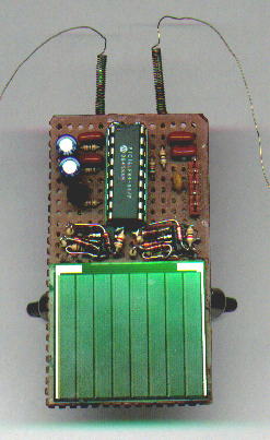
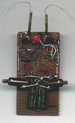
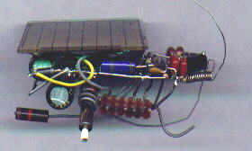
I made my prototype LF84 popper on a piece of perfboard 2.7 by 1.5 inches with the 3733 solar cell occupying half of it. Unless you're really good at miniature construction techniques go bigger or make the solar cell separate from the controller board to help space it out. To make it fit, I had to use free-form technique to make the H-bridge assemblies then mounted them as components. For effective popping, the robot must be balanced. The LED is the front skid but you don't want all the weight on it. When it fires, it should lift the LED off the ground. A wire prevents the robot from tipping back too far. The touch sensors can be made by coiling up guitar string into a spring and suspending a wire inside, for mine I temporarily borrowed the touch feelers from my photopopper.
The Zetex H-bridges are surface-mount parts, fortunately they're larger than typical smd parts so it isn't too hard to solder wires and parts to them. If new to free-forming practice on other tiny stuff first, it takes a bit of practice. It would be really cool if I had a PC board with lands for the bridge chips, on my wish list.
A more reasonable and compact layout would have been to spread out the H-bridge components and elevate the solar cell on top of the bridges, maybe next time. Use your imagination, layout is not critical but try to make it as light as possible and don't forget about balance.
June 26, 1999 - I got into a mad scientist mood last night, and produced a tiny PicBot II using a few parts "borrowed" from my original 5x picbot. It uses Tiny Pager Motors from Solarbotics, and weighs about 5/8 of an ounce. The circuit is mostly like the posted circuit except that it does not have protected bridges (too lazy to add the diodes), no LED (got the other one to debug with) and uses 470 ohm resistors between the PIC and bridge input diodes (had tiny 470's but no tiny 1K's). Oh yea, omitted the extra 2.2uF rail cap and 5.1V safety zener. Works great! Now to arrange some sort of protective shell around both of them to keep 'em from shorting each other out, probably doesn't hurt anything but still...

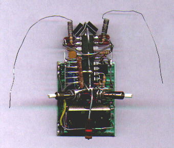
(got to do something with those old 1K 20% 1/2W resistors...)
Parts List...
Parts for the robot... (DK# = Digikey number)
1 - PIC16LF84-04/P PIC processor - DK# PIC16LF84-04/P
1 - 18 pin IC socket - DK# A9318
2 - Zetex H-bridge chips - DK# ZHB6718CT
1 - 1381-L voltage trigger - DK# MN1381-L
10 - 1N914 or 1N4148 diodes - DK #1N4148MSCT
1 - 5.1 volt zener diode - DK# 1N5231BMSCT
1 - Schottky diode - DK# 1N5817CT
2 - 1 farad 2.5 volt AL-Gold capacitors - DK# P6963
2 - 2.2uF capacitors - DK# P6261
2 - 0.1uF capacitors - DK# P4525 (min 10)
2 - 0.022uF capacitors - DK# P4517 (min 10)
1 - 27pF capacitor - DK# P4017A or 1306PH (min 10)
2 - 100 ohm 1/8 watt resistors - DK# 100EBK (min 5 on resistors)
1 - 470 ohm 1/8 watt resistor - DK# 470EBK
8 - 1K 1/8 watt resistors - DK# 1.0KEBK
2 - 15K 1/8 watt resistors - DK# 15KEBK
2 - 3 meg 1/8 watt resistors - DK# 3.0MEBK
1 - 10 meg 1/8 watt resistor - DK# 10MEBK
1 - red high-efficiency jumbo LED - DK# 160-1127
1 - 5 pin header for programming port - DK# WM4003
2 - pager motors - Solarbotics
1 - "3733" solar cell - Solarbotics
2 - IR photodiodes - Solarbotics
2 - spring-type feeler switches (can make with a thin guitar string)
... heatshrink, perfboard, and other common stuff
Parts for making a programmer... (battery powered version)
1 - 5.1 volt zener diode - DK# 1N5231BMSCT (*)
1 - 12 volt zener diode - DK# 1N5242BMSCT
1 - 100 ohm resistor
1 - 180 ohm resistor (*)
2 - 1K resistors
1 - 2.2K resistor
2 - 4.7K resistors
1 - 10K resistor
1 - 5 pin connector housing - DK# WM2014
5 - connector pins - DK# WM2200 (min 10)
1 - 25 pin male D connector - DK# 225M
2 - 2N3904 transistors - DK# 2N3904
2 - 9V battery clips - DK# BS12I-HD
2 - 9V batteries
1 - DPDT switch (1 leg switches 9 volts to 180 ohm, other switches 18 volts
to 2.2K)
... multi-wire cable and batteries if you make the programmer
... a PC that can run the PIC programming software
(*) extra parts to supply +5 volts to the robot through programming port pin 4 - 180 ohms from 9 volt battery on ground side (through one pole of switch) to cathode (band) of 5.1 volt zener and pin 4, anode of zener to ground.
For powering with an AC adapter supplying about 18 volts DC increase the 180 ohm resistor to about 470 ohms and connect to the +18 volt supply. For powering with less than 18 volts, such as the 14 volts put out by cheap 12 volt adapters, reduce the 2.2K resistor to about 1K or so and eliminate (short) the 100 ohm resistor.
The programmer parts list and modification notes apply to David Tait's SPP in-circuit programmer design, any programmer that supports the 'F84 and can read the SPASM-assembled hex can be used.
For reference, here is a (ascii) schematic of the programming hardware I am using...
  Parallel Port                                        Robot
  -------------                                        -----

   2   D0 o---------------1K----------.
                                      |
   3   D1 o-------------------1K------|-----------------o RB6  1
                                      |
   4   D2 o-----------4.7K--.         *-----------------o RB7  2
                            |   c     |
   5   D3 o---4.7K---.      |   .-----|---.         .---o GND  3
                     |      `-|<      |   |        _|_
  10  ACK o----------*      b  _|_e   |   |   .---------o +5V  4
                   c |                |   |   |
  18- GND o--.        >|---15K--------'   *---|----*----o MCLR 5
   25       _|_    e_|_ b          .--1K--'   |    |
                          .---*----*---470----*    |
  15-20v  >---------|>|---'  _|_+            _|_/ _|_/
   ac/dc  >---.              -.- 470u  5.1v //_\ //_\ 12v
             _|_             _|_ 25v    ZD   _|_  _|_  ZD

  transistors = 2N3904, 2N2222 or other NPN
  ZD = zener diodes, 1/2W  other diode = 1N4001 etc
Software Considerations...
A programmable robot is useless without software to run on it. The main idea for solar operation is to monitor the 1381 voltage trigger and only function if there's adequate power otherwise go into a power-saving sleep mode and let the capacitor charge from the solar cell. It is useful to not trigger right when the voltage is high, but wait a while longer and let the power build up so that it can pop around for a while instead of just once or a few times. Makes for a much better show even if little difference in distance travelled per time period.
There are two main ways to approach control, hard-coded or learning. The PIC-bot II software allows assembly of either version plus the selection of various other options, change the "pgoptions" equate at the top of the source. The hard-coded fixed response code emulates a photovore with very basic navigational skills, the learning code learns and remembers moves that enable it to clear obstacles. The simplest learning scheme is a simple memory, the processed environment bits are the address, the data is the remembered move. If the move proves to be less than useful, the data is randomised in the hopes of finding something that works better. This is the basics of Reenforcement Learning (RL). The simple scheme can be enhanced by using confidence tags to mark the memories, memories that work have their confidence increased up to a maximum (usually 3), memories that fail have their confidences decreased. Only when confidence reaches zero is the memory replaced with a random move. This is the essence of Heiserman's "beta" algorithm. A more advanced "gamma" scheme takes high confidence memories and spreads them to low confidence memories that might represent a similar situation.
For RL, the trick is when to give the "learn" signal. Simple rules can be relearn the last move if both the current environment and the last environment had feelers touching, or if the last move resulted in backwards or no motion but the feelers weren't touching. With these rules the robot quickly learns that if it pops in a circle it can avoid feeler contact and occasionally gets stuck in repeating moves that happen to satisfy the rules. Additional rules can be applied to discourage circular behavior, like detecting too many identical moves in a row or giving it an extra reward for photovoric behavior.
Many other AI methods can be used but keep in mind most conventional techniques are too intensive to run on tiny microcontrollers like the PIC. I don't see mapmaking anytime soon but remembering sequences of moves is possible.
Hardware Design Notes...
So far this seems to be a superior design than the original 5x-based PIC-bot, even not counting in-circuit reprogramming. The original sometimes locks up after running totally out of power, momentarilly shorting MCLR (pin 4) to ground brings it back to life. I have not seen this effect using the PIC16LF84 processor. One thing that bugs me slightly about both designs and a possible concern - the datasheets recommend that the pull-up for MCLR be under 40K, ha! it's 10 MEGS in my arrangement although the trigger out does bring it to within a few hundred millivolts of V+ when the power is high. Good enough? The purpose of the RC on MCLR is so that the chip will reset on a slowly rising supply, if it becomes a problem change it to say 1M/22uF or something like that but I have seen no problem with the resistor being 10M, the MCLR pin is measured less than 70mV from V+ so oh well.
IR photocell "eyes" are specified, but other photocell types should work if you tweek the capacitor values and/or photocell read code. To use CdS cells, make the capacitors 0.1-0.22uF rather than 0.022uF and eliminate the time delays from the read code (CdS has MUCH lower resistance than photodiodes, also consume a bit more power). Regular LEDs have useful photo characteristics, haven't tried but they probably can be substituted directly for the IR photodiodes with only tweeking of the time delays in the read code.
Code Notes...
(understanding below not required to use, just trying to explain some of the available code options...)
When the program starts, it checks the voltage by reading the 1381 output, and if low it goes to sleep, checking every few seconds as dictated by the watchdog timer. When there is sufficient voltage, it doesn't come alive right away (unless starting for the first time) but waits for either something to change in the perceived environment, or after checking so many times as defined by "maxsleep". This allows extra power to build up while still remaining responsive. Once it wakes, it moves many times in short bursts. The "pops" variable determines how many moves it makes per waking cycle, "popdur" controls how long each burst lasts. At the end of a cycle, if it still has adequate voltage it begins a new cycle of movement, otherwise it goes to sleep. While it is awake, movement is controlled by reading the feelers and photocells and deciding which way it should go using either fixed or learned responses, defined by bits in the "pgoptions" constant. If bit 0 (learning) and bit 1 (fixed if low power) are set, the robot will explore and learn when there is good power, when the power is low it finishes out the current movement cycle using fixed photovoric responses to help get it closer to the light. In learning mode, the "maxconfidence" constant determines how permanent memories are, 0 to simulates a simple memory (changes anytime something goes wrong) while the maximum of 3 gives memories up to 4 chances to work before being replaced. The constants "calibrateL" and "calibrateR" control the light sensitivity of the photocells, "darkthresh" defines the light level that equal light goes from "00" to "11", and also when 'dark' bits come on if that option is selected. If bankmem is selected, 2 bits from the last action are used to address the next action for sort of a sense of sequence. Alternatively, the previous 'bad' environment flags can be used to select the memory, for another sense of sequence. This option is intended to be used with the option that relaxes how it defines 'bad' moves, normally a move is bad if the robot is reversing when the current environment is good, if the relax option is enabled, it's a bad move only if reversing when the last three environment readings were good. Only one of the three expansion options bankmem, usedark and usebadbits should be used, last one takes precedence.
March 14 - version 1.19 - modified gamma routine so that it only gammas memories with the feeler bits set, I want it to develop independent memories when the feelers are not touching. What was happening before is the robot would try say left motor forward with neither feeler touching, being not against the rules and usually successful it quicky reached max confidence and spread to all other (blank because it just started) memories and the robot thought it was ok to do that anytime feelers weren't touching. Whatever it came up with first became the default behavior despite the photo inputs, useful for the robot but sometimes not very interesting to watch. A few lines fixes that, however there is no code that specifically tells it that it can't run around in circles so it still might learn to do that, until power gets low and it scurries to the light. It's doing its thing so I guess I'll allow it... as long as it doesn't get excessively boring. My other versions of this kind of software often had a boring move counter - every time it executed the same move a counter is incremented, if different the counter is cleared, if the counter exceeds a certain number the move is discouraged. If it comes to it...
Here is a hex dump and memory analysis for version 1.19 after popping around for a day.
3/24/99 - version 1.20 - finally got to me, added anti-circle code. If the robot makes maxsame (7) identical moves in a row, treated as bad move. Any move that is different clears the "boring" counter.
Here is a hex dump and memory analysis for version 1.20, after about half a day. Better...
Other stuff...
5/17/99... aquired a scanner, not bad. Sure looks better than ascii!
6/25/99... David Tait's site is gone, but there are mirrors:
Dontronics: http://www.dontronics.com/dtlinks.html
Sam Powell: http://come.to/thepicarchive
Adam Davis: http://www.ubasics.com/adam/pic/archive.shtml
Brian Lane: http://www.tatoosh.com/picarchive/
The page you probably want is icp84.html, or "In-circuit 16F84 Programmers" but look around, tons of neat PIC stuff.