All trademarks mentioned here are the property of their
respective owners.
Here's my Amp Mods document (PDF
6.9M), it details a bunch of guitar amp mods and rebuilds I did,
mostly from the '90's while working for Shiloh Music but some a
little more recent. Back then it was economical to get a
silverface Fender from a pawn shop for cheap (didn't matter much
if it was broken) and gut some or all of it and create a new amp,
typically with an overdrive channel and an effects loop. 3/12/22 -
Updated with a "new" Bassman mod that recently came into the shop
for maintenance, also slightly edited a few things for clarity and
fixed a gruesome overlapping image glitch caused by loss of image
attributes after doing an edit elsewhere (note to self always
check everything after every edit no matter how minor).
Here's a page about using JFETs, a
transistor type that comes close to working like a tube.
Here's an Electronics Calculations program
I made using Free Pascal (last mod 1/18/21)
Here's my Find
Closest Resistor Value program I made with QBasic/FreeBASIC
(last mod 5/14/25)
Content on this page:
All information here is provided as-is and without warranty, use
at your own risk. Tube amplifiers use lethal voltages, do not
attempt to build these circuits unless experienced in high voltage
safety procedures and are familiar with building tube amplifiers.
These are not construction plans, many details are omitted. Rather
these are ideas to inspire and to document some of the things I
make.
Update 5/14/25 - Good things often come to an end - I'm no longer
working at Superior Music, Chuck is moving his music store to
Michigan and although he invited my to tag along that won't work
for me (day job and not into massive amounts of snow). I'm still
doing limited repairs for myself and friends but for the most part
out of the amp repair business. It was getting harder and harder
anyway, they don't make stuff like they used to and walk-in
customers often didn't understand why I couldn't work on their
stuff. Pretty bad when a 60 year old amp is no problem at all but
can't get parts or service info for a 10 year old amp. Solid state
amps got to be a huge problem as the was-common through-hole
transistors and chips became unobtainium (or counterfeit).
For the Smokin Tone and Purple Cow pedals Chuck is looking for a manufacturer for them and if/when that can be arranged will be selling them through his new Superior Music store. Alternatively if we can at least get the cases drilled I can make more of them, but (especially now) I have no desire to have bits of aluminum everywhere. This is pretty much why I only made a few. However I've always been open about my circuits, if you just want one for yourself and know about electronics the basic circuitry for both of these pedals is on my JFET page. If you are interested in manufacturing them get in touch with me or Chuck.
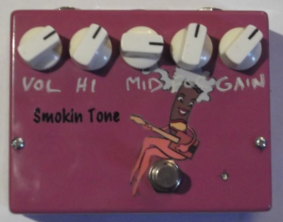
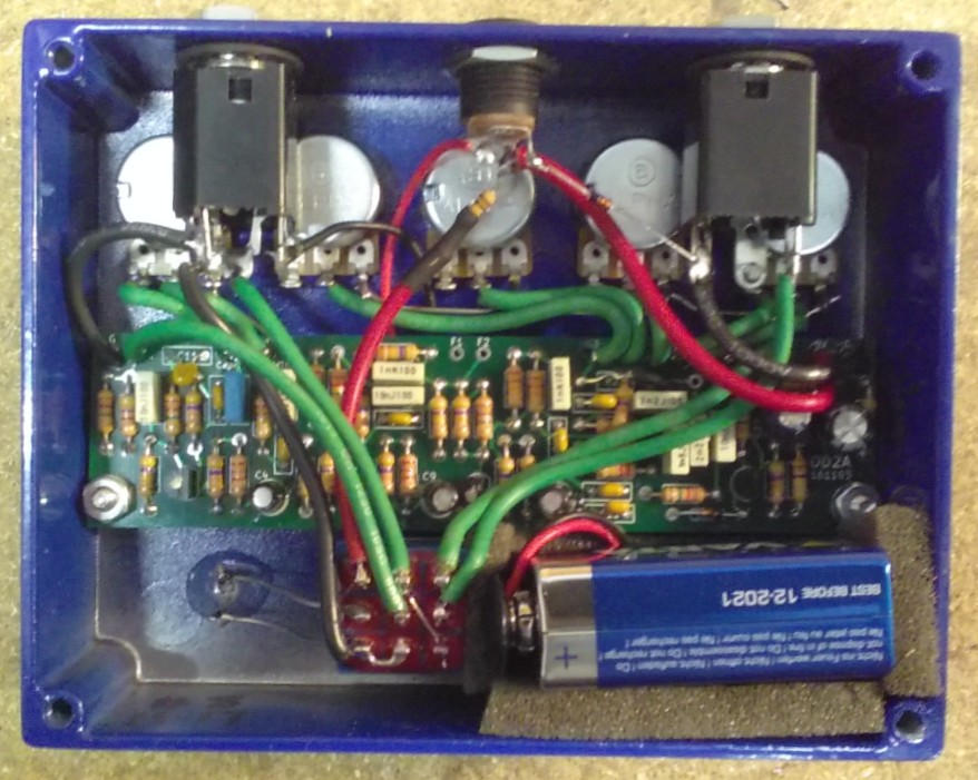
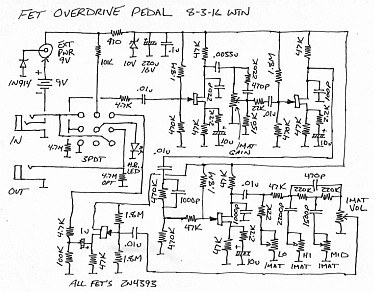
12/13/17 - This is a JFET-based overdrive preamp that can be
dialed from almost clean to heavy distortion. The design has three
gain stages with a compensated gain control between the first two
stages (at low gain it boosts the highs, at high gain it cuts the
lows), a fixed high boost between the last two stages, and tones
after that - inspired by my amp mods and not coincidently it
sounds a lot like a high-gain tube amp. The stock design has a
true bypass switch but can be wired to leave the unity-gain output
buffer in place even when bypassed. Very low current drain, less
than 2ma and most of that's for the LED.
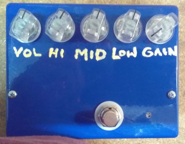
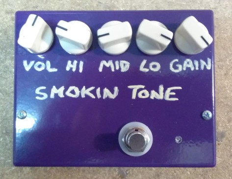
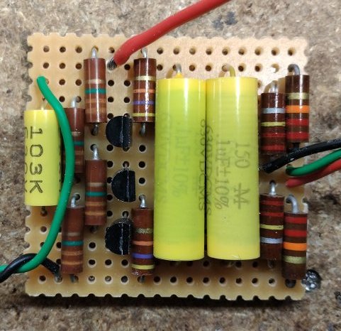
Here's an early one in light purple (can't get that case anymore)
and later ones in blue and dark purple cases...
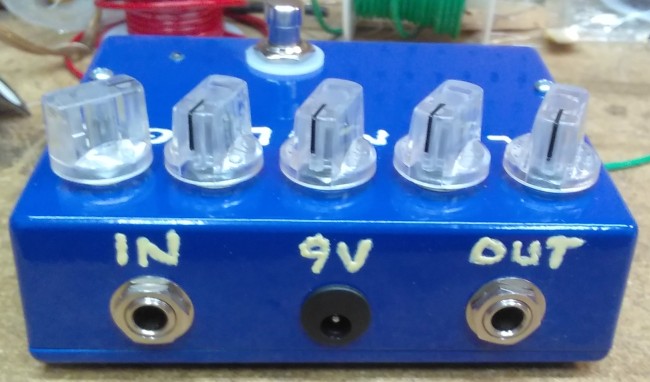
A view of the insides...
Eventually I'd like to get someone else to make the cases
pre-drilled with professional silkscreening but for now just
making them myself as needed and labeling as requested or however
I feel like. Order from the SmokinTone
page, $179+tax. Customizations are available, including case
color and doodling, more or less gain, optimizing for bass (more
lows, more output, less gain) and always-buffered output.
6/3/25 - As noted above in the page notes, Superior Music has
moved back to Michigan so not sure when I can make more of these,
but if I do I will do it through Chuck. Plus he's got the rest of
the pedal parts. Here's the schematic for the original
prototype (the 470K in parallel with 1000p was replaced with a 1MA
"focus" control), this simulation is closer to the production
version. More about this circuit is on my FETs page.
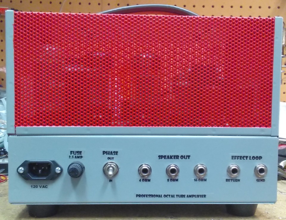
The Smokin
Tone "Professional Octal Tube Amplifier" Head
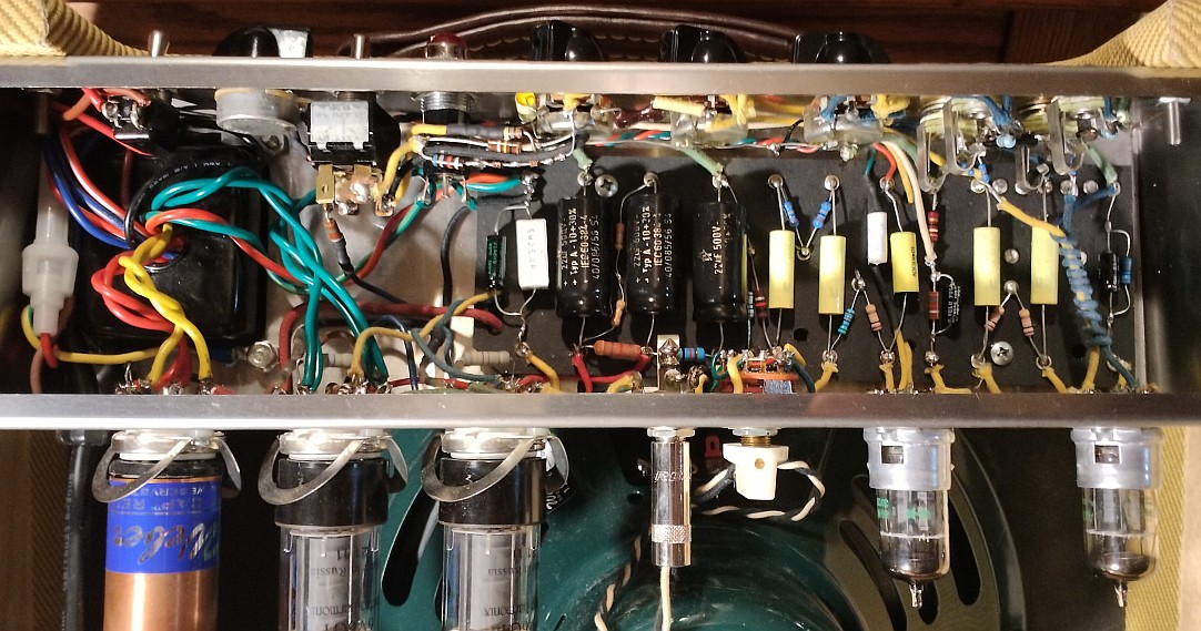
12/13/17 - Recently I built a compact tube amp head for Chuck
Kotlarus...
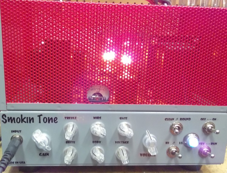
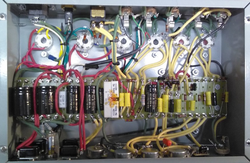
Specs for this particular amp...
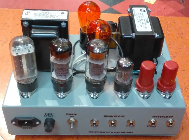
A cool thing about this amp is the low power switch that inserts
two 11 watt bulbs in series with the output transformer center
tap.. the bulbs pulse with the signal and because it's a class-A
amp, they dim when it goes into clipping. I've seen a lot of
schemes for reducing output power (usually done by switching to
triode wiring or varying the screen voltage) but never tried the
obvious - just put a resistor in series with the output
transformer feed. That worked but a resistor there gets very hot,
so used light bulbs instead.
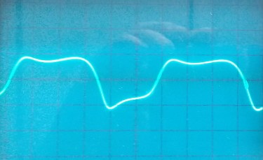
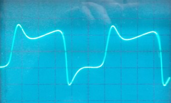
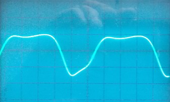
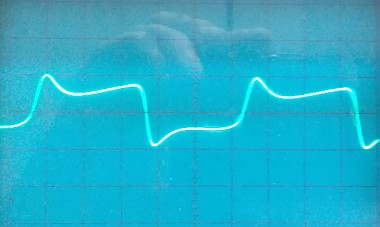
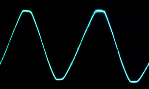
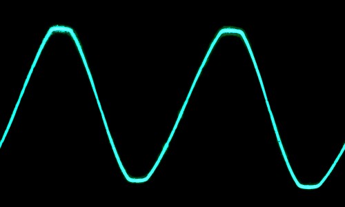
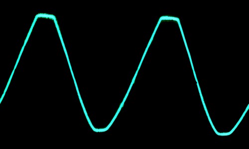
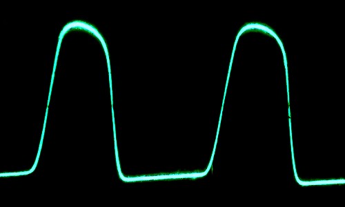
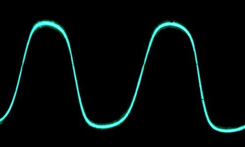
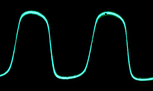
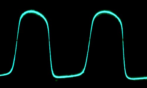
Scope shots for normal, round and low power settings...
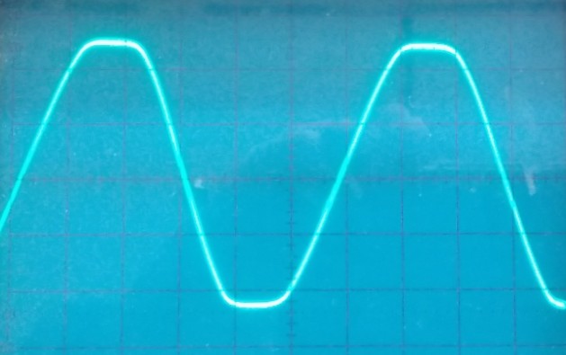
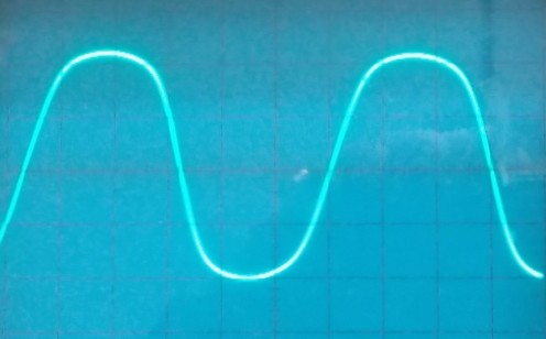
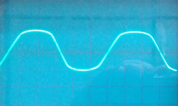
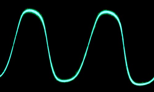
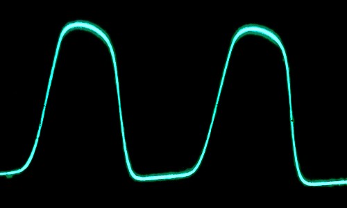
Overdrive with different gain and voltage settings...
Cool stuff!
Planning on making another one just like this one and maybe some
other variations, I love the chassis. Possibilities include using
common 12AX7 preamp tubes (6SJ7's are rare and often noisy), gain
or channel switching, and a class AB configuration for 40 to 50
watts output power. It's very hard to predict what another
musician will want in an amp - some like two or three knobs, some
want independent channels and output power needs vary widely. At
Skully's Saloon where I play and run sound even a 15 watt amp can
be too loud, but a downtown country gig might need 100 watts of
clean. For what I do a simple gain switching scheme where it just
boosts the preamp gain and drops the output level works for me.
Others need full channel switching or no switching at all because
they use pedals for that. So for now treating it like an amp
mod... customer tells me what they want then I make it.
6/5/20 - Here's the original schematic of the Pro Octal Amp...
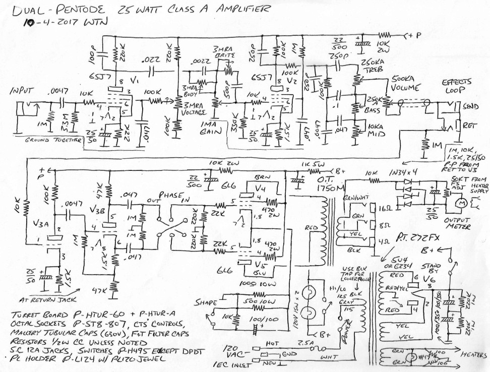
This shows the voltage control connected to the 1st stage but
ended up moving it on the 2nd stage instead where it can better
alter the tone. Originally wanted to use it to set the first stage
gain but the operating point shift had too much impact on input
overload. There is no negative feedback in the power amplifier
section, making it possible to flip the phase by reversing the
power tube grids. Other than using old octal pentode preamp tubes,
there's nothing that special about the preamp design other than
the compensated gain I usually use - this time with variable low
and high pre-clip equalization. The post-clip tones are
traditional with an extra cap on the mid so that it doesn't also
boost highs as much. The real coolness is using light bulbs in
series with the output transformer supply feed for the low power
function. Surely someone has thought of it but haven't ever seen
an amp that does this. At first I used resistors but to achive a
useful power reduction they had to be in the 1K range and got
quite hot, so replaced the resistors with light bulbs. This is a
class-A amp so the full power and zero power current is similar
(in this amp full power current is actually a bit less) so there
isn't a whole lot of dynamic effect, would be interesting to try
this trick with a grid-biased class-AB amp.
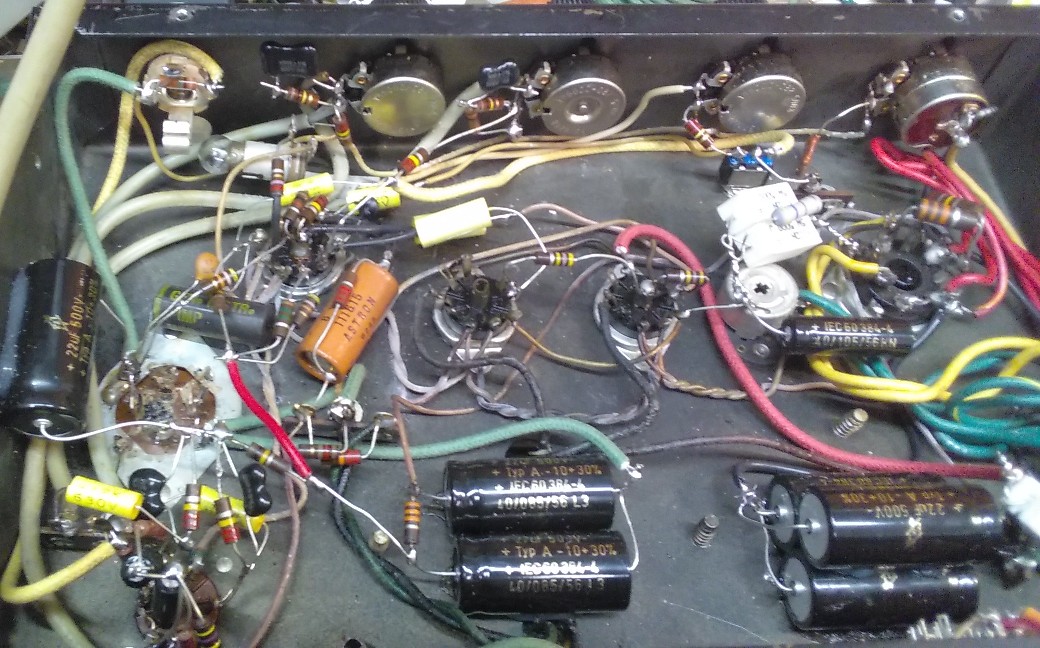
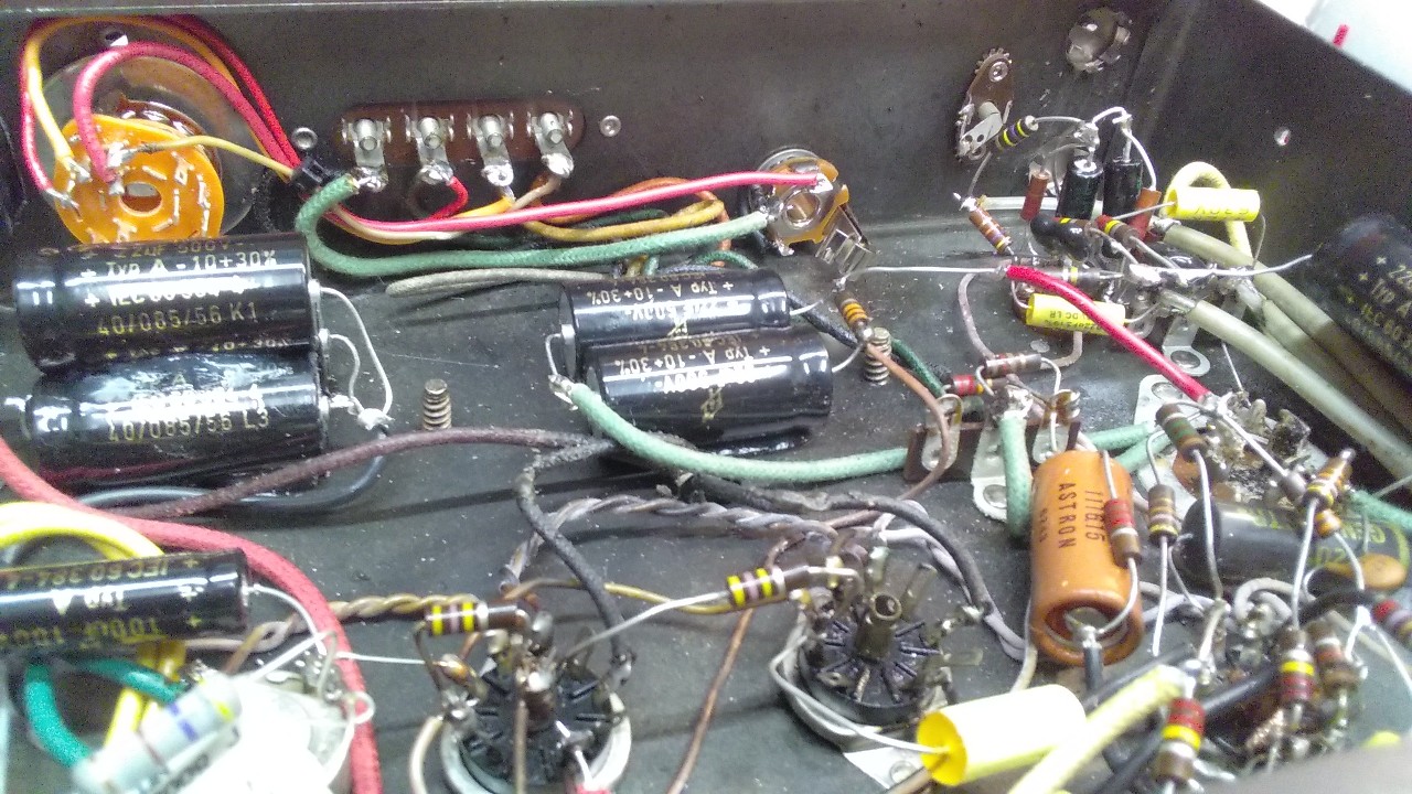
Stromberg
Signet 22 (SAU-22) Mod
This is a cool little amp from around 1960, puts out about 20
watts with a pair of EL84's, a 6U8/7687 pentode/triode gain
stage/phase inverter and a 12AX7 preamp tube. They're fairly
common and make a nice mod amp, so far I've done three of them
(two for Chuck, another for a customer who had one and heard the
first one I did for Chuck). The original amp is a simple PA
amplifier with two screw-on type mic inputs, a RCA ceramic
phonograph input, four knobs for the inputs and tone, and
terminal-strip speaker connections. Before even bothering with
doing too much I change out the filter and coupling capacitors
which are usually toast and make sure the basic bones of the amp
are good.
Here are some pics I made of the original rough mod schematic and
mods 2 and 3...
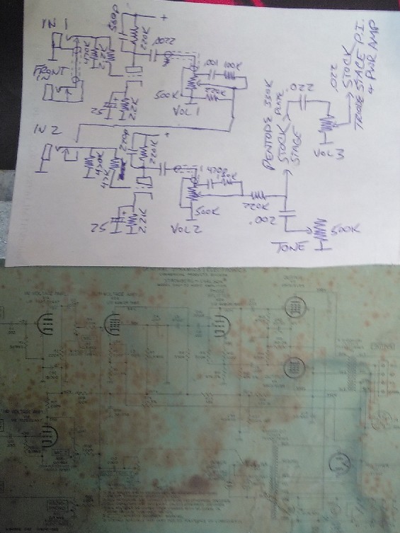
Neither mod matches the original schematic - every amp is
different and has different needs. Mod 2 on the top apparently has
no plate cap at all on the 2nd stage, and an extra cap on the
phase inverter output at the power tube grids. Also has no front
input jack. Mod 3 looks like it has a cap on the pentode plate
resistor, and also has a toggle switch to select whether the tone
control is after gain 2 or after the master. Also left in the
original pentode stage bypass capacitor. Basically when I do mods
I play guitar through it and experiment with various filter values
until I'm happy with the tone. On both these mods added an extra
filter stage for the EL84 screen grids (470 ohms plus 22uF), on
the original they were connected directly to the main output
transformer supply.. yuck. The extra resistance limits the screen
grid current to keep the tubes happy and lowers the hum level.
6/5/20 - A better schematic of the first two versions of this
mod...
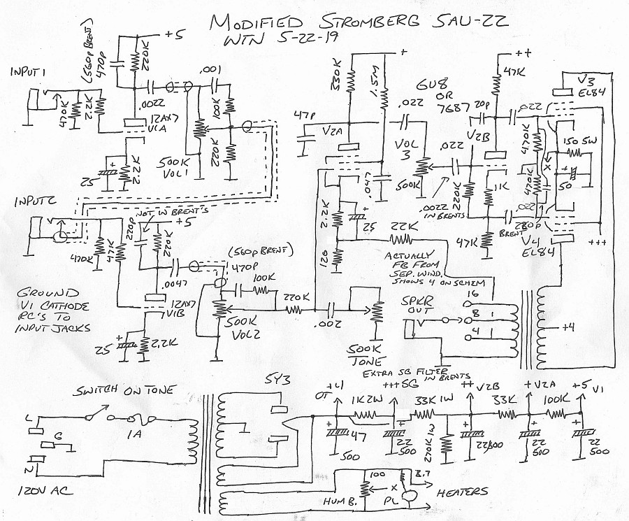
The tone position switch on the 3rd mod adds a 220K after the
wiper of volume 3, then switches between the resistor after volume
2 and the resistor after volume 3. The preamp resembles my 3-stage
overdrive design but using a pentode rather than a triode for the
3rd stage adds a lot more gain - it needs the extra gain control
to tame it down and be able to get clean tones. Having the preamp
clip stage in the power amp feedback loop has the effect of
lowering the gain as the master volume is increased.
Modified Vibrochamp with a Solid State
Phase Inverter
This has got to be one of the funniest things I've done to a tube
amp but it came out surprisingly well. Customer had a blackface
Vibrochamp and wanted it to be louder to take on the road... on a
good day a stock Champ output is maybe 4-5 watts into 4 ohms
(stock was 3.2 ohms) and it had an 8 ohm speaker in it so it was
maybe pushing 3 watts. Well sure, could go even 50 watts with
Bassman transformers but the replacement speaker had a huge magnet
on it, no way 6L6's will clear that so had to be something with
6V6's. At first was thinking Deluxe-like but before doing that and
ordering transformers and cutting holes and stuff in a vintage amp
thought I would try to see what I could do with the stock power
transformer and something more minimal and reversible. First
thought was to use the existing 6V6 to drive a 2nd 6V6 for push
pull but testing that idea in LTspice showed it to be flawed.
Simple idea but the 2nd tube will always be an inverse of the
first tube (once the gain is balanced) so no way to get class AB,
at best just doubles the output with the same (ugly weak)
single-ended distortion. Adding a proper Princeton-style phase
inverter fixed it in simulation, able to get about 15 watts clean,
but as I was already putting another 6V6 on the heater line wasn't
keen on adding another 12AX7 to the heater winding, plus the whole
punching a hole in a vintage amp thing. So thought just use a
transistor phase inverter. Which would have been awesome if I had
a 500V 1W+ high gain transistor hanging around. Got 160V 600mW
2N5551's though, maybe I could stack 3 together? Why yes I can!
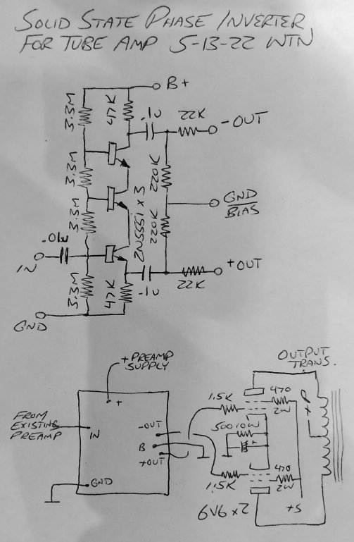
The resistor values could probably be optimized further but these
were the components I had on hand and seem to work well. Using a
solid state rectifier (a pair of 1KV 1.5A diodes) and an output
transformer I had laying around was able to get about 12 watts
into 8 ohms and about 15 watts into 16 ohms, roughly equivalent to
a Princeton. Didn't touch the preamp section, it had already had
the negative feedback disconnected.
The following simulations show more about what's going on with
varying levels of drive (click for bigger images)...

The floating emitter/collector notes get a bit "spiky" under
heavy overload, not sure what's up with that but the spikes do not
appear on the phase inverter outputs and with the output tubes in
full saturation it isn't going to be heard anyway. Using the stock
2n5550 LTspice model here but it's the same with another 2N5551
model. Adding 1000pF or 0.01uF capacitors to the floating base
nodes mostly make the spikes go away by clamping the emitters to a
mostly constant voltage, but that actually puts more voltage
stress on the transistors. Letting the emitter and base nodes
float and do whatever they want provides better voltage
distribution, keeping the maximum voltage on each transistor to
under 160 volts even with the spikes (if they are even real).
Every node is current limited so even if there is some breakdown
it's not going to matter much. Here are the LTspice files
if interested, the tube models were found on the web. The idea for
using LTspice's uniform RC-line symbol for a potentiometer came
from "analogspiceman's" tube
amp simulation files, awesome idea that avoids having to add
a symbol file.
An LTspice simulation of an entire tube
amp
This simulation borrows ideas from analogspiceman's tube amp
simulation, the control and tube models are adapted from the
Fender5E7Bndmstr.asc file, the rectifier tube models are from
Duncan Amps, adapted to use a triode symbol to avoid having to
make a new rectifier symbol, so the schematic looks a bit funny.
Most aspects are simulated - power transformer, ripple, filter
capacitors, sag - but the transformers are "perfect" other than
winding series resistance. That's fine by me, in my opinion if one
can hear transformer effects then it's either inadequate or being
overloaded.
Here's the LTspice schematic...
The simulated amplifier uses three 12AX7 tubes, a JFET for
driving the effects loop, two 6L6 tubes, and one 5AR4 or 5U4
rectifier tube. The preamp is a three-stage design with a gain
control between the 1st and 2nd stage and a drive control between
the 2nd and 3rd stage. The gain control has both low and high
frequency compensation, the drive control has low frequency
compensation. The preamp is followed by a cathode follower driving
the tone stack and volume control, which feeds a unity gain
N-channel JFET buffer driving the effects loop send. Choice of
JFET isn't critical, doesn't even have to be a JFET, an NPN
transistor works just as well. The preamp design is typical of the
kind of stuff I make but haven't built this exact design (yet),
usually I just have a single gain control in conjunction with a
clean channel or some other way to drop the overall gain. In this
single-channel non-switching design the additional drive control
provides a simple way to clean it up or go full-on dirt.
The extra circuitry around 3rd stage V2a and cathode follower V2b
is to provide more symmetric 2nd-order filtering - high frequency
filter C10 is connected directly across V2a so its effect is
asymmetrical, R13 and R12 attenuate the signal to drop it to
effects level (after passing through the tones/volume), and C11
provides additional more symmetrical high frequency filtering. R45
and R46 shift the DC down to avoid exceeding the 12AX7's
cathode-heater breakdown voltage, C26 bypasses R45 so that the
full AC signal is applied to the cathode follower.
The power amp (from the effects return) has a 12AX7 gain stage
V3a with a rather large plate resistor for maximum voltage gain
(to reduce the effects loop level), feeding a single stage unity
gain phase spliter which feeds the 6L6 power tubes with fairly
large (56K) grid resistors to avoid too much asymmetric shift when
overloaded. There is no overall negative feedback. Resistor R35
between the OT supply and screen grid supply is moderately high
(1.5K) for a bit of sag compression, can be smaller or a choke for
tighter response. 1 ohm resistors R32 and R33 are for setting the
bias, Rpca and Cpca are only for the simulation, for measuring the
average current through V5. Rload represents the speaker, Rf1,
Rf2, Rf3, L10, L11, C30 and C31 are only for the simulation to
mimic high frequency speaker response, although a basic
compensated line output could have a similar design. Originally I
tried the simulated speaker model from the 5E7 simulation,
although probably more accurate it distorted the output waveform
making it hard to tell how close the output was to a real tube amp
- I'm used to using a pure resistive load when bench-testing
amplifiers. With the resistive load it looks pretty much identical
to what I'm used to seeing on the scope.
The power supply is pretty much like a typical tube rectifier
amplifier - ignore the grid in the 5U4 symbols and both sections
are in one envelope. Rrectfil represents the rectifier tube
filament, Rheaters represent the 12AX7 filaments. D2 and D3 in
series with the rectifier tube plates is a common trick for
keeping the rectifier from sparking/shorting from power surges.
TR1 is the bias control. V3, V6, Ddc1 and Ddc2 are not part of a
real circuit, they are only to briefly pre-bias the simulation for
setting a useful DC operating point so that static node voltages
and component power dissipations will be useful, the initial pulse
voltages are set to be similar to the zero signal supply and bias
voltages. The GigaOhm resistor Rleak is only for the simulation so
that it doesn't complain about a floating node, there should be no
connection between the AC primary and ground. The power switch,
fuse, standby switch and pilot light are omitted from the
simulation schematic. Although the simulation is mostly complete,
it is not intended to be plans for making a real amplifier - do
not attempt to build this unless experienced in these things and
you know how to fill in the missing bits.
Here's are low gain high volume transient simulations with 5U4
and 5AR4 (GZ34) rectifiers... (click images for bigger)
The 5U4 rectifier has lower output and more sag under load,
whereas the 5AR4 delivers more power and a tighter response. In
the simulations the 5U4 is clipping at about 24V peak/17V RMS,
equivalent to about 36 watts into 8 ohms at clip, and the 5AR4 is
clipping at about 28V peak/19.8V RMS, equivalent to about 49 watts
into 8 ohms at clip. Thereabouts.. output power in a real
amplifier is highly affected by the power and output transformer
specs.
Here's how it responds to an actual guitar signal at low gain
(with a 5AR4) and at higher gain (with a 5U4)...
Nice. Here's the low gain simulated output, and the higher gain simulated output (converted to MP3 files). Not exactly what the amp would actually sound like but close, at least about what it would sound like into a dummy load with a simple 7K LP filter "speaker emulator" output. Here's a zip file containing the LTspice files and the original input sound file.
6/20/25 - The 12AX7 model used in the original 50W amp simulation
wasn't accurate, added a better model and made it the default.
There was a math error in the AUD20 potentiometer model causing it
to not go all the way to zero, fixed. Finally the 1N4007 model
conflicted with the model included with later versions of LTspice,
renamed to 1N4007SM. Here is the updated
zip file and the updated
MP3 output file.
Here are some plots of the new simulation... (click image for
bigger)


The old DM 12AX7 model worked fairly well in this simulation...

...however that model didn't work well at all in the 5E3
simulation, which uses 1.5K bias resistors, was hard to get it to
clip on the bottom part. The new 12AX7 model works better, less
rounding on the bottom and simulated output sounds smoother.
1/18/26 - Lately I've been playing around with speaker models and
the results have been somewhat shocking and not in a good way,
more like in the smoke might come out kind of way. The impedance
of a speaker varies greatly with frequency, an 8 ohm speaker is
only about 8 ohms over the range of about 120khz to 1khz, below
that there is a resonance peak where the impedance rises to about
30 ohms depending on the cabinet loading, and (more critically)
above that the impedance rises without bounds due to the
inductance of the voice coil. At 20khz the impedance can exceed 50
ohms, almost an open circuit, this is what happened when I tried
Mod12-50 parameters...

Yes it's peaking over 1.8KV positive and a kilovolt negative,
that is frightening. The 6L6 model in the original simulation
didn't show this effect (plates clamped at 0V), this is with the
Duncan 6L6 model. The spikes are more pronounced on one side
because of a asymmetric filtering of the "fizz" suppressor cap C10
which filters less at the bottom of V2a's stroke where the
impedance is the lowest, allowing more high frequency content to
get through. It's worse when the power amp itself is clipping. Not
all speakers are this extreme with impedance rise but the fix is
trivial - add flyback diodes to the output tube plates to keep the
plates from going negative...
Much better! Clamping negative excursions keeps the positive
excursions safely under 1000 volts. Some claim this removes some
high end sizzle but as the frequencies involved are above the
speaker's range there isn't that much of an effect (I can't tell
in the simulations) and frankly I don't want to hear that kind of
"sizzle" in my output, sounds like mosquitoes in heat to me and is
why I pepper caps all over to suppress it. I like smooth, leave
the sizzle to the drummer. The diodes also help protect the output
transformer from loss of load but the output tubes will still take
a beating from excessive screen grid current, always a situation
to avoid but at least with the diodes it isn't instant fry. The
diodes must be rated for high voltage, I use three 1N4007 diodes
in series and heatshrinked for each plate.
The speaker model is pretty cool, it uses Thiele/Small parameters
along with Le tweaks and cabinet and filtering parameters...
The parameters and resulting plot are made-up and don't
correspond to any particular speaker, rather I dialed it in with a
lower resonance more like one would get from a closed-back
cabinet. Could be lower. Also this model doesn't rise in impedance
as drastically at high frequencies as with the Mod12-50 parameters
so it doesn't hit the flyback diodes as hard.
Much of the math in this model was derived from a paper I found
on the internet, it has been modified to include an additional
resistor and inductor in parallel with the voice coil inductance
to better match the impedance curves of real speakers (the
effective inductance decreases with increasing frequency due to
eddy currents and stuff). The T/S parameters are on the first "+"
line immediately after "params:", Repf and Lepf are multipliers
that set the R/L in parallel with Le, which is recalculated so
that the combination has the same impedance at 1khz, together with
Le they help match the resulting impedance curve to published data
(not exactly but close enough, I usually go for trying to match 2K
5K and 20K). Vb sets the cabinet volume, Ql is the cabinet Q at
the speaker resonance, I don't really know what h is but it does
stuff (something to do with the port). Finally I added a high
frequency "peaking" filter to the output as the original model
didn't have enough high frequency rolloff over about 7Khz, Lfi
sets the filter inductance, Rfi sets the peaking.
Here is a schematic of the model...
Cout is fixed to 2.7uF, Rout is one microohm (in the original
model current through Cout represented the output but LTspice
doesn't allow that for AC analysis), Cfi1 is 1.5uF and Cfi2 is
1uF. MULT is a multiplication function to recover the weak output
signal from Rout, 10E7 times OutLevel. In the raw model OutLevel
is set to roughly equal the input level but when using the model
to derive a wave output it has to be much lower (typically 3 or
so) to keep the output signal from exceeding +/-1, usually it's
overridden and specified by the symbol calling the subcircuit.
Here is the speaker model in text form...
* Speaker model with modified Le and peaking output filter
* some calcs from https://www.micka.de/en/download/spice-tsp_en.pdf
* T/S and cabinet/filter parms made up to make it look like what I want
.subckt SP4 0 in out
+ params: fs=50 Vas=40 Qts=1.3 Qms=10 Re=7.2 Le=0.5m
+ Repf=6 Lepf=0.3 Vb=100 Ql=0.3 h=0.4 Lfi=0.35m Rfi=17 OutLevel=150
+ ws=6.28318*fs c=345 rho=1.18 Cab=Vb/(rho*c*c) wb=h*ws
+ Qes=Qts*Qms/(Qms-Qts) Cas=Vas/(rho*c*c) Cmes=Qes/(ws*Re)
+ Lces=1/(ws*ws*Cmes) Res=Qms/(ws*Cmes) Lceb=Lces*Cab/Cas
+ Cmep=1/(wb*wb*Lceb) Rel=1/(wb*Cmep*Ql) Rep=Re*Repf Lep=Le*Lepf
+ Lez=(1/((1/(6283.18*Le))-(1/(Rep+6283.18*Lep))))/6283.18
Eout  7   0   VALUE={V(5)*1E7*OutLevel}
Cfi1  8   0   1.5u
Cfi2  out 0   1u
Cout  4   5   2.7u
Rout  5   0   1u
Lfi   7   out {Lfi}
Rfi   out 8   {Rfi}
Lez   in  1   {Lez}
Lep   in  6   {Lep}
Rep   6   1   {Rep}
Re    1   2   {Re}
Res   2   0   {Res}
Cmes  2   0   {Cmes}
Lces  2   0   {Lces}
Rel   2   3   {Rel}
Cmep  3   4   {Cmep}
Lceb  4   0   {Lceb}
.ends
Here is a new wavefile simulation using this model with the gain
and drive controls maxed... (and a new lick yay)


Here is the resulting audio
output. Here is a zip file
containing the new tubeamp11 simulation files, a test sim for the
speaker model, and the grunge lick input wavefile.
A bit about grounding and other shop
horror stories
11/23/24 - I see a lot written about "star grounding" and how it's the magic thing that solves all noise issues etc, but no. It has its place, but is generally only useful for avoiding potential shifts and induced ripple noise with power-consuming circuits. Beyond the the power stages, not so much and in some cases can be very detrimental. I worked on this one amp that took it to the extreme.. the grounds for just about everything all went to a single point. It sucked! Noisy, and unstable and short of totally rewiring was hard to tame. Here's why.
Every signal flow has the signal, and the return current. These
like to be right next to each other, especially at higher
frequencies. Also, the "ground" (cathode side) of a gain stage is
really an inverting input, and to avoid amplifying unwanted
signals needs to be connected to the ground of the signal source.
For example, for the first tube stage, the cathode resistor and
bypass capacitor needs to be connected to the ground of the input
jack, and the cathode resistor and bypass capacitor of the 2nd
stage needs to be connected to the ground side of the gain
control. Once past the 1st and 2nd stages it doesn't matter as
much but in general anything with a control that goes to zero
should be treated that way, so that when the control is down
(guitar volume or gain control) then there is no potential between
the grid and cathode circuits. The grounds should be as parallel
as possible with the signal wires, ideally through the shield (but
be careful not to add too much grid to ground capacitance),
because otherwise any opening between the runs forms a one-turn
transformer secondary coupling any magnetic fields into the gain
stage. Once wired this way, then where the input jack and gain
control doesn't matter much, generally to the chassis but doesn't
have to be, point is to not amplify any difference between those
two ground points.
Now about that star ground... this amplifier ran the grounds for
the input jacks and cathode circuits all the way across the amp to
the common ground point which also had first stage filter caps and
all sorts of nasty stuff connected to the same point. So instead
of the return current of the input jack going a few inches to the
first stage, it has to travel about 3 feet with lots of
opportunity to pick up noise along the way (remember the ground of
a gain stage is actually another input). No matter how well bonded
the star ground is, at high gains even a few microvolts of ground
potential difference can produce a noticeable hum and a millivolt
difference is a loud buzz. However when stages are properly
grounded to their signal sources they are much more tolerant of
ground differences between the stages, only noticeable when the
gain is cranked with no ground noise at all at minimum gain.
The way I do my tube amp grounds is to run the negatives of the
first two filter caps to the center tap of the power transformer,
attached to a ground lug to the chassis (so that the buzz-rich
filter cap return noise runs straight back to the power
transformer and not through the chassis). The cathodes of the
power tubes should be grounded somewhere near this point - a lot
of the time I don't like relying on single screw-connected grounds
so often will have another ground lug and run a wire between the
transformer/cap and output ground lugs. Where the rest of the
stuff grounds to doesn't matter that much so long as it grounds
(eventually) to the chassis and not the power grounds, and later
stage filter caps are grounded near the stages that they feed -
loops in the power supply can also pick up noise so helps to run
the filter cap hots and grounds together.
I like hard-grounding the input jack (and other jacks) to the
chassis so if there's a fault it doesn't go through the wiring. A
popular preamp grounding method is to run a length of buswire from
the input jacks to the backs of all the controls and ground stuff
to that, however that makes it harder to replace controls and
control backs aren't exactly securely grounded and do become
loose. A better way is to add a few ground lugs (at least two or
three) and run a length of buswire between the lugs and also to
the input jacks. Some internet "wisdom" says multiple grounds
cause ground loops and everything must be grounded separately...
but that's only true if there is current running through the
ground loop, and stages aren't properly grounded to their sources.
Otherwise multiple grounds increase reliability and if there is a
larger loop, it actually serves to absorb hum and RFI in the
vicinity - but stages have to be individually properly grounded or
the current through the loop can become audible.
So.. star grounds - good for power stuff, good for making sure a
group of systems are all running at the same ground potential. But
don't route low level signal returns through the star ground.
Also on this same amplifier, the small-value resistors usually
found in series with the power tube grids were mounted on the
board instead, and it did not like the JJ tubes I installed, had a
totally wacked output waveform. Adding 1.5K resistors in series
with the grids at the sockets solved the problem (didn't bother
removing the existing 1.5K resistors). Also had to add extra 680
ohm grid resistors to a couple of the preamp tubes to keep them
stable, likely to counteract the effect of the shielded wiring -
high gain tube stages don't like too much capacitance connected
directly to the grid.
Here's another one I ran into just last week... had one of those
newish (2010) tube amps (a Blackstar HT 60) chock full of solid
state stuff in for repair, in addition the usual issues - worn out
noisy tubes bad connectors etc - after awhile it would start
popping and crackling, and the output waveform didn't look all
that great but these days it's hard to tell if that's intentional.
Otherwise the amp sounded great with a really nice overdrive
channel, definitely worth saving. It had an oddball phase
inverter, a pair of mosfets driving a 12AU7 tube state. A couple
of resistors were visibly overheated with the color code markings
discolored so found the schematic to verify the values (22K 2W)
and replaced them. Better but was immediately obvious they were
running too hot, one especially (from the voltage readings it was
dissipating about 4 watts, no wonder it was complaining). Looking
at the schematic I noticed they were coupling the mosfets to the
12AU7 grids through a 1uF 450V electrolytic capacitor... sure
enough there was about 1V on one grid and 10V (!!) on the other.
Replaced the electrolytic caps with 0.2uF 630V film caps (2 0.1uF
in parallel), that fixed it, the resistors only dissipate about a
watt each. Still a bit on the hot side but not a problem. Going to
a lower value for the coupling capacitors was not a problem as
they're feeding a ~500K impedance putting the -6db point at about
1.6hz. So yay for having a schematic available, making it a fairly
easy fix. The sad part though is likely every one of those amps
will eventually fail - don't use electrolytic coupling caps for
tube stages.
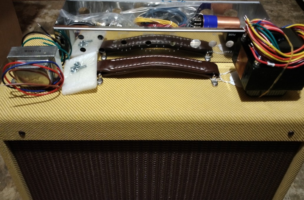
6/4/25 - The 5E3 Deluxe Kit I
ordered from Weber Speakers has arrived!
10/8/25 - The last four months have been an interesting journey
and this build has gone in many directions in my quest for 5E3
goodness, but it was loading down this page so the previous notes
have been moved to the 5E3 Development page.
When I ordered the kit I intended on internally coupling the
channels and adding a master volume, but beyond that I didn't know
what else it would need, had to get it together to see what I had.
This was one of the cheaper kits available, it came with
everything needed to build the amp (besides 6V6 and 12AX7 tubes,
came with a "copper top" rectifier) but to keep the cost down most
of the internal electronic parts were imported. I didn't care
about that (and it was fully disclosed), was going to replace
stuff as needed anyway. I mainly bought it for the cabinet,
chassis and the Weber speaker, which were all top notch! This kit
is for experienced builders, there are no instructions other than
a schematic and a layout.
When I got it together the first thing I noticed was it had way
too much gain, I couldn't get the volumes much over 2 before it
got dirty and it wasn't exactly a pleasant kind of dirt. This is a
consequence of the original backwards volume controls to simplify
the control and tone circuitry, basically they shorted the output
of the first stages to set the volume and "came on" very quickly
as the controls were advanced. Also at higher volume settings the
0.1uF coupling caps were operating into a fairly high impedance so
if not careful there was a lot of low frequency "blocking"
distortion. Need something to cut the gain down at lower volume
settings and do something about the excess subsonics.
A trick with the 5E3 circuit was to plug into the bright channel
then use the unused normal channel to load down the output,
improving the control taper. So the first thing I tried was a gain
reduction switch (first time I recall doing a gain reduction mod
to an amp) that switched in a 100K resistor from the output of the
control network (at V2A grid) to ground, that worked very well and
finally I could adjust the volume controls without them acting
more like switches. Eventually the mod switch was wired to provide
stock, negative feedback and load settings, and ended up adding a
diode/resistor network across the 100K load resistor to improve
the overdrive tone at high gain when using the load setting. When
the switch is in the stock position all that is undone and it's
mostly stock, just with a master volume and the bright channel
connected to the normal channel through a 1000pF capacitor when
plugged into the normal channel.
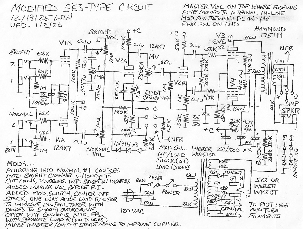
1/2/26 - This mod has been through a lot of revisions in the
quest for tone. I wasn't crazy about the original negative
feedback mod which used a 39K feedback resistor through the 25uF
bypass capacitor to the 1.5K cathode resistor for V2A, then
grounding the minus end of the BP cap disabled the NFB mod for
stock. This is how I'd seen some mods on the net do it (except for
the way I was switching it in and out), but it caused too much
gain loss. Eventually I rewired it so that it was more like a
Princeton-type negative feedback circuit where the
pre-phase-inverter stage cathode resistor is always bypassed and
feedback was provided by a separate voltage divider, 2.7K and 47
ohm for the Princeton but I used 1.5K and 39 ohm for a bit more
negative feedback. This produces a less drastic volume change
permitting me to move the switch to the top panel without
unpleasant surprises, and the new switch wiring also permitted
adding a separate load resistor to improve control taper in the
negative feedback position.
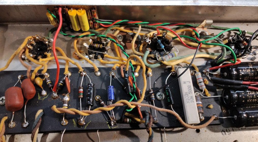
Here's the schematic...
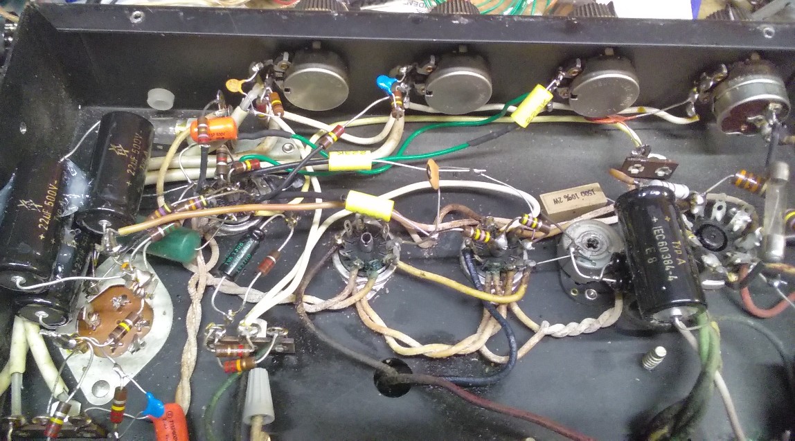
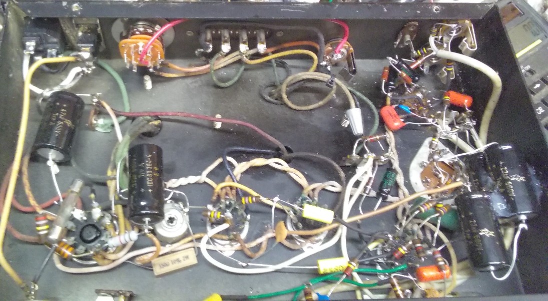
Here are some pictures of the insides... (before I drilled the
extra back hole and still has the original mod switch hole)
Some scope shots, forgive the fuzziness. Just past power amp
clipping in the stock, NFB and load positions...
The smoothing diodes have a slight effect on the power amp
clipping symmetry, the NFB position is best for clean.
Preamp distortion in the stock position...
This was with a 70mV 420hz input and the normal volume at 8.5, 10
and 11, bright volume all the way down and the tone half way. What
is not evident here is the blocking distortion on low notes caused
by grid conduction driving the tube into cutoff. Preamp distortion
in the NFB position is similar but not as radical as the added
load resistor limits the blocking effect from grid conduction.
Preamp distortion in the load position with diodes to balance out
grid conduction...
This is with both the normal and bright volumes at 9, 10.5 and
12, it still flattens a bit at high drive levels but remains
mostly symmetrical and most of all prevents blocking distortion
even when cranked wide open. Looking at it now I should probably
add one more 1N914 to the diode string to keep it from getting
into the cold side too quickly, which would also improve clean
performance in the load position. Might play around with that
later but it sounds pretty good the way it is... mods are never
really done as I have discovered. It's not as important now that I
have a better-behaved negative feedback mod with a more moderate
load without diodes that splits the difference between load/diode
mod and stock.
Here are some things I recorded with this amp, all at low volume. These are with my pedals, a Mooer Ninety Orange, my Purple Cow, a Mooer Echolyser and sometimes a Mooer Sweeper. The first two had some post-recording processing, the "licks" are right as they came off my DR40 other than normalizing. Recorder was placed in the back of the cabinet.
7/2/26 - Just one little thing was bugging me... the now unused
hole in between the preamp tubes, so had to fill it with something
at least semi-useful - a bright switch. Used a double-through
center-off switch to select between 250pF, none, or 500pF
bypassing the bright volume control. To avoid extra wiring I
connected the capacitors between V1B plate and V2A grid, with 10M
resistors on the switch side of the caps to avoid pops when
flipping the switch. With this mod I can explore the lower reaches
of the tone control and dial in more bass boost and mid scoop
without losing highs, I like it!
7/18/26 - I used the DIYLC
program to hack out a neater schematic of the circuit that
includes the bright switch...

Cool stuff! I love this amp!
LTspice Simulation of the modified
5E3 circuit
10/8/25 - Previous [and latest] notes have been moved to the 5E3 Development page to
avoid clogging this page up too much.
But this is neat... The following stepped simulation shows the
preamp distortion without the smoothing diodes connected...
It all bunches up on the bottom side of the waveforms,
corresponding to the "cold" side of V2A when the signal slams up
against the rail with no limiting. This is with the diodes
connected...
Adding the diodes makes a huge difference! However it also
slightly affects the clean, especially at higher temperatures. The
following two plots show power amp distortion at 60C without the
diodes and with the diodes...

The difference is subtle, just a bit more rounding on the cold
side.
Terry Newton (wtn90125@yahoo.com)