The other main tone-affecting mod is using a 1000pF capacitor to couple the normal channel into the bright channel's #1 jack switch to provide a low-frequency rolloff to reduce blocking distortion.
10/7/25 - This 5E3 build has been a work in progress, going
through many different phases and ideas and redo's, and in the
process was clogging up my main electronics
page too much with details and clutter that often became
outdated when the next idea came along. But it was still a process
I'd like to preserve, so moving it all to this page so I can
streamline the material on the main page.
12/19/25 - Modified the mod switch wiring... Load mod with diodes
stays the same, Stock is now the center-off position, and the
Negative Feedback mod now uses a different circuit that avoids
excessive gain loss. Details below.
There are two sections here, the details of the amp build below
and the LTspice simulation stuff
after that.
Caution! Tube amps use potentially lethal voltages, do not
attempt to service or modify tube amps unless experienced in
safely working around high voltage circuitry. In particular the
stock 5E3 design does not have "bleeder" resistors and can retain
high voltage for a long time when not powered, always safely
discharge the filter caps through a low value resistor (100 to 470
ohms) before doing any work. All information is provided as is and
without warranty.
6/4/25 - The 5E3 Deluxe Kit I
ordered from Weber Speakers has arrived!
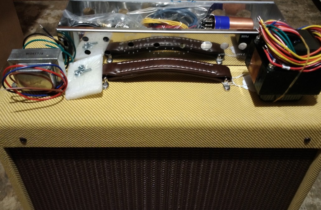
This kit is for experienced builders, it does not come with
instructions beyond the schematic and layout linked from the web
site. It's cheaper than some other kits as it does not include
tubes (except for a Weber Copper Cap rectifier) and the
transformers and other electronic parts are sourced overseas but
that's OK I'm cheap too. I'll probably replace the filter caps
with 22/500 FT caps but other than that as long as it works I
don't care where the parts came from. The cabinet and chassis are
top-notch made in USA with a Weber alnico speaker already
installed, that's what really matters. It took awhile to get the
kit (over 3 weeks), like they made it just for me! Oh and it comes
with a cuzy... [rest of this post and the next deleted, was a good
start but got better once I better understood the circuit]
6/11/25 - It's together!
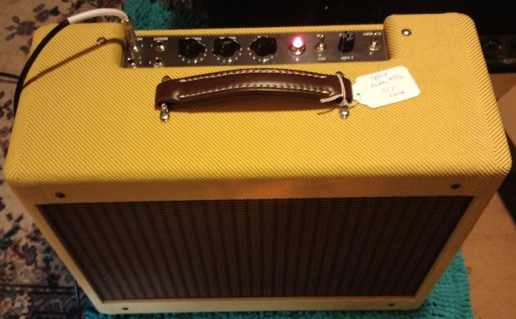
Construction went well, everything needed was included but I
added a few extra things I wanted - green wire for the filaments
(the kit included lots of blue but nah gotta have green), 3/8"
lockwashers to go under the jacks and controls, a couple of solder
lugs, an 8/32 nut and a lockwasher to avoid having to solder to
the chassis, and some things not part of the original design -
470/2W screen grid resistors (habit), an extra 0.1uF cap and 250KA
control for a master volume, two 330K bleeder resistors, two
1N4007 diodes in series with the rectifier tube plates to avoid
sparking when using a real rectifier tube, and a 1000pF mica cap
to link the channels when nothing is plugged into the bright
channel #1 jack (a simple wire link didn't work out). I did use my
own 22/500 F&T filter caps and a Sprague 25/50 bypass cap
across the 250/5W cathode resistor, and lost one of the 1.5K
resistors for the 6V6 sockets so used my CC's, otherwise used all
the supplied parts. The resistor legs weren't long enough to span
the full width of the fiberboard but that wasn't an issue, the
affected ones were bypassed by capacitors which did fit so just
soldered the resistors to the capacitors first. Most of the
smaller resistors were 1% type and kind of hard to read, used a
meter to make sure I had the right values. It took about one long
day to assemble the kit and get it working, not counting the
tweaks I made after assembly.
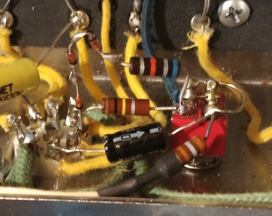
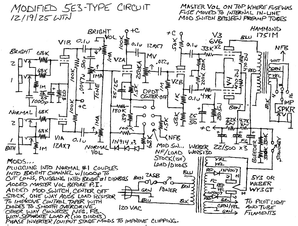
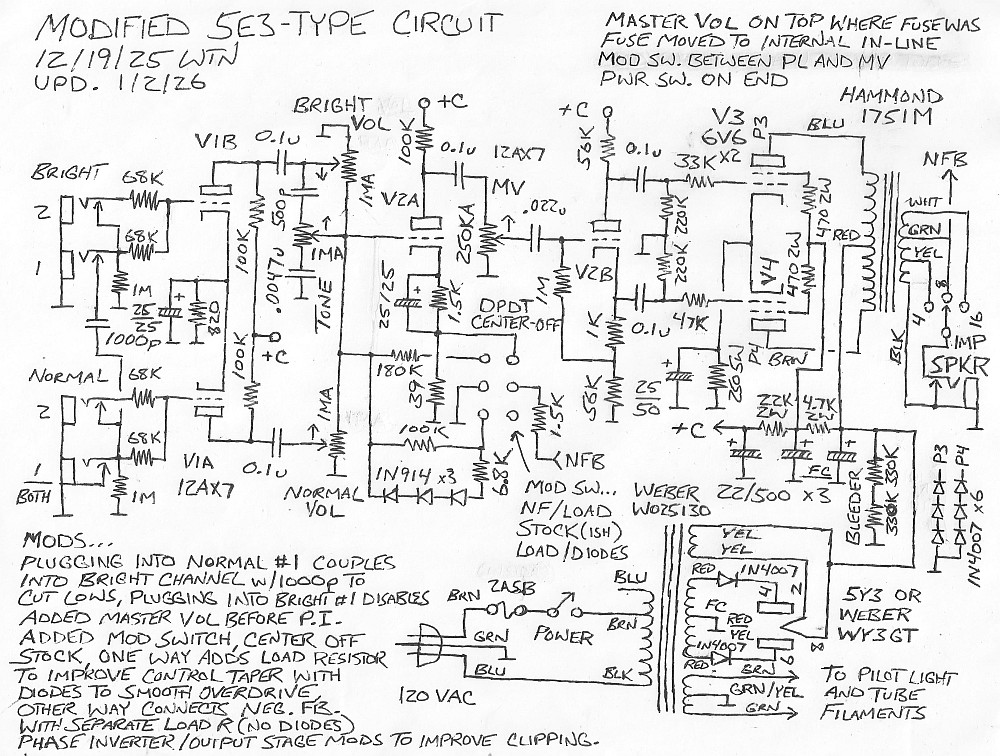
Here's a schematic of the modified 5E3 circuit [updated to include the gain reduction mod]...

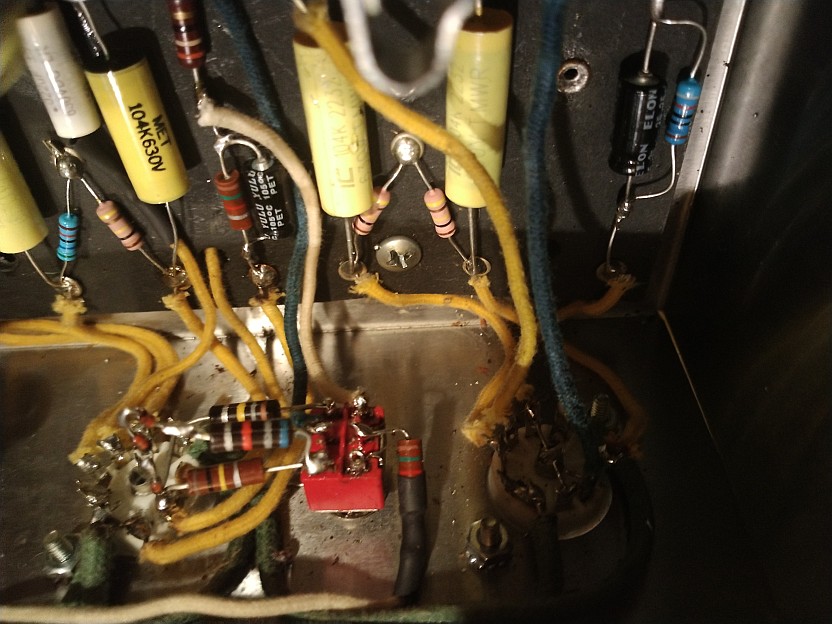
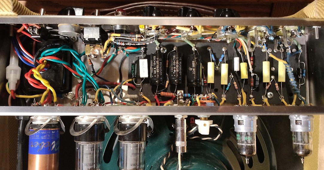
Here are some pictures of the internals...
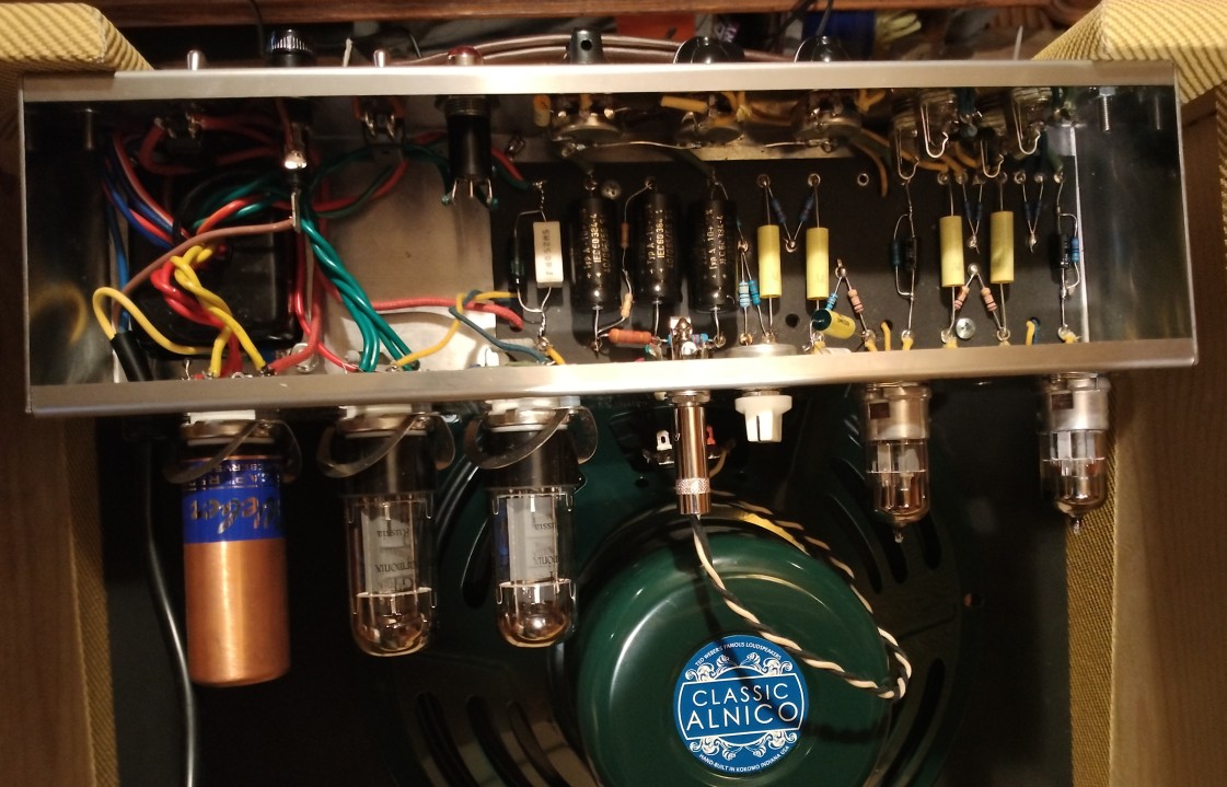
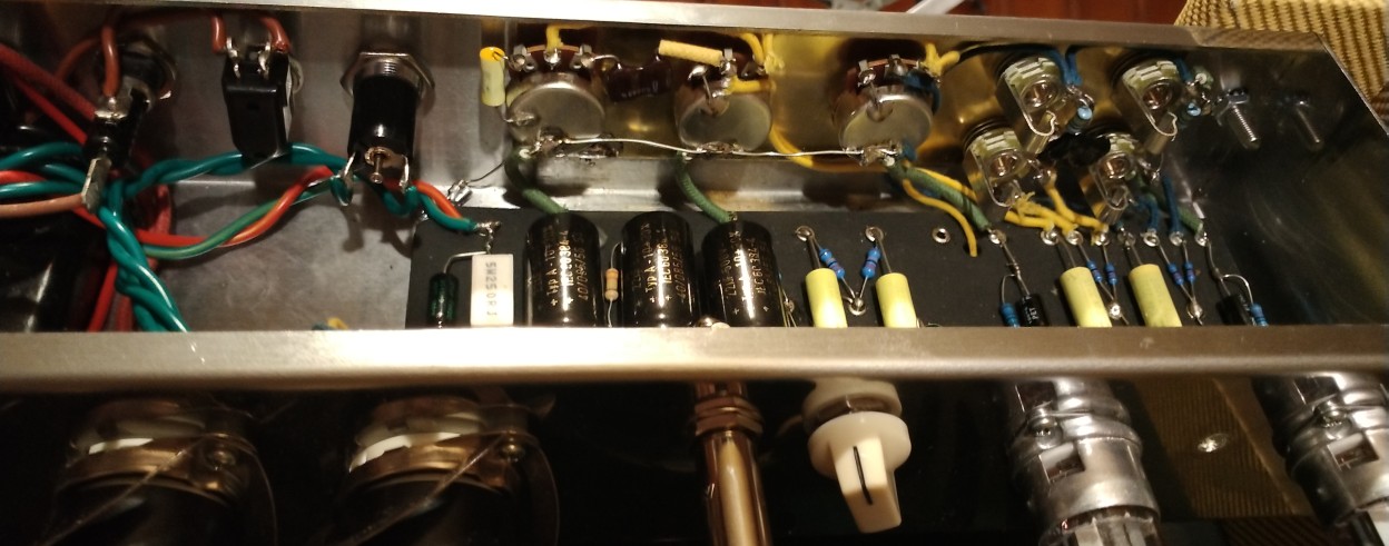
The hole between V1 and V2 is where my failed gain boost switch
was.. this circuit doesn't need any boosting.
I ran the transformer center taps directly to the fiberboard to
ensure no supply ripple current flows through the chassis. Ran a
wire across all the pots and grounded to the brass plate and
chassis to ensure loose backs don't cause issues. Actually didn't
really need the brass plate, other than soldering a strap to the
chassis didn't solder anything else to it.. but it looks cool.
Instead I just soldered the grounds to the (strapped) pot backs
and soldered the V1 cathode R/C ground directly to the input
jacks. As much as possible kept the grid and cathode circuits
parallel to each other. The amp is very quiet.
I've worked on 5E3's in the shop, but this is the first time I've
really gotten down and dirty with the circuit. And dirty it is! I
was surprised at how much gain it has, and the backwards-wired
volume controls... well that just ain't right but it's part of
what gives this circuit its character. It's the opposite of
compensated gains like I'm used to - it increases lows to the
subsonic range as the volumes are increased. When I first put it
together with a simple wire channel link it was a disaster, if the
volumes were over about 5 string movement would overload it making
it cut out. The 1000pF link cap solved that, but it's still
unbridled, anything over 2 to 3 is in the breakup range. I like
it!
But I'm tempted to add a gain reduction switch... getting a clean
tone is somewhat difficult, can't get the volumes more than a
notch before it starts to distort. One way to do that is switch a
resistor from V2A grid to ground, but that would also affect the
tone control response. Another way would be use a double-pole
switch to switch in a pair of resistors from the control wipers to
ground.. hmm... a DPDT center-off switch could do both... Yes! The
switch centers are grounded, the side towards the back connects a
100K to V2A grid, the other side separately connects a pair of 39K
resistors to the volume control wipers. Thus center is stock,
pushed in is attenuated, pulled out is loaded. The 39K load
position decreases the total gain by about 8db, keeps the bass
response from going subsonic at higher settings, and helps smooth
out the control taper. The 100K attenuation position doesn't drop
the total gain that much when the volumes are all the way up, but
greatly smooths out the control tapers, have to get to around 6 to
start getting breakup. The tone control still works fine.
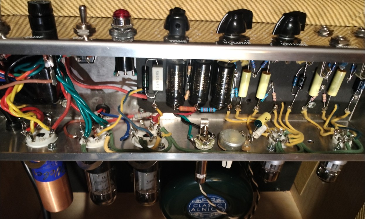
This picture shows both the master volume mod and the gain
reduction mod...
I think I am close to 5E3 perfection, the beast has been tamed
yet it's all still there when I want it.
6/17/25 - Ran into a semi-minor issue... was getting a pop when
plugging into the amp, indicating there was some DC coming out of
the inputs. Checked it with a meter, sure enough with an open jack
cord was reading about 300mV out of the normal input and over
500mV out of the bright input. Changing V1 had no effect. While
not much it's enough to cause pedal switches to pop and other odd
effects. The cause is apparently the fiberboard - in high humidity
environments (like my basement) it absorbs moisture and becomes
slightly conductive. Verified that by directly probing the
fiberboard in the vicinity of the B+ eyelets... yep it's slightly
electrified. Not enough to cause operational issues but enough to
cause switching pops. Compounding the problem was the switch
contact on the normal #1 input jack wasn't making contact,
probably should have replaced them with Switchcraft 12A jacks but
for now just cleaned and tweaked them.
I've seen the leakage issue many times with fiberboard-based
amps, and the solution here is the same as always, get those
sensitive 68K input resistors off the fiberboard and solder them
directly to the jacks. The front end wiring now looks like this...
This completely solved the issue, input offset is now less than
1mV and no pops at all.
Normally fiberboard leakage isn't much of an issue, but it has
been very humid here in my basement lately, up to 90% at times.
After the amp had been on for awhile, driving out moisture, the
stray voltage into the nearest (now empty) eyelet had dropped to
only a couple hundred millivolts. My meter has an input impedance
of about 20meg so that corresponds to about 10mV in the usual 1meg
circuit, far less than I measured earlier so the issue appears to
be self-correcting. However, I prefer that my pedal switches not
pop when I first turn on the amp in a humid environment.
6/18/25 - Playing around with my pedalboard...
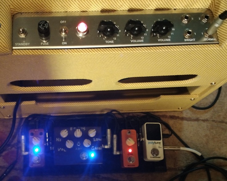
From right to left that's a TC Electronic polytune tuner, a Mooer
Ninety Orange phase shifter, my Purple Cow overdrive, and a Mooer
Echolizer delay. The amp volumes are cranked pretty hot and the
gain reduction switch is in the stock position, so the echos
distort together. The master volume is quite low. Here's what it sounded like.
That was recorded with a DR40 inside the cabinet, post processing
was just adding a bit of bass and reverb and normalizing the
level.
I like this amp!
6/21/25 - I took some measurements and scope plots from the amp.
With 121V AC line voltage, at idle B+A is 369V, B+B is 319V and
B+C is 248V. That's 0.53 watts on the 4.7K 2W resistor. 6V6
cathodes are 19.2V, V1A and V1B plates are 170V, V1 cathodes are
1.3V, V2A plate is 166V, V2A cathode is 1.25V, V2B plate is 202V
and V2B cathode is 45.4V. Output power is 9.9 watts into 8 ohms
and 13.8 watts into 16 ohms, at the onset of clipping. At clipping
into 8 ohms, B+A is 357V, B+B is 291V (0.93W on the 4.7K) and B+C
is 227V. With heavy clipping into 8 ohms, B+A is 343V, B+B is 271V
(1.1W on the 4.7K) and B+C is 213V.
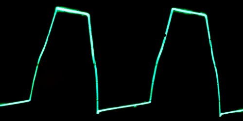
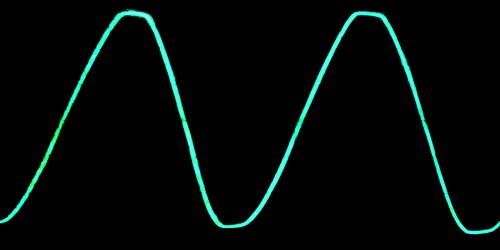
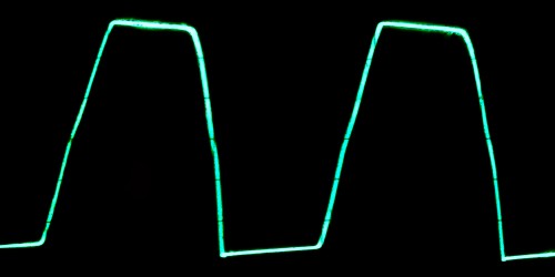
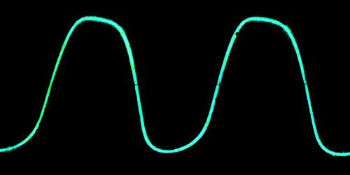
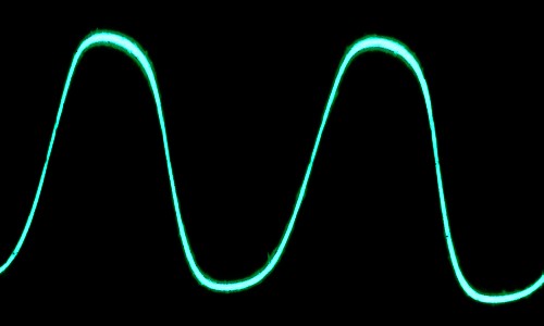
The following scope plots are rough, taken with my phone with
glare which I gamma'd out, ignore odd waveform tilting.
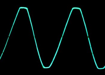
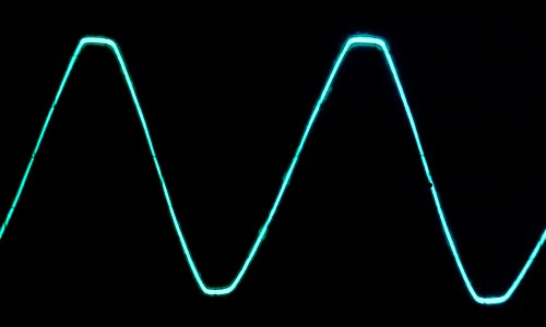
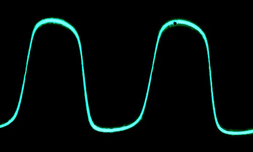
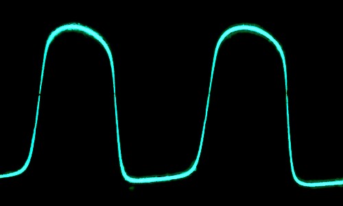
Output into 8 ohms...
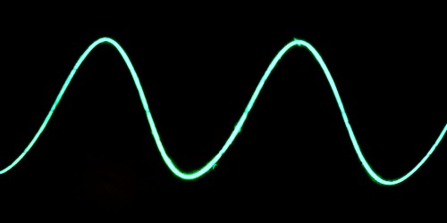
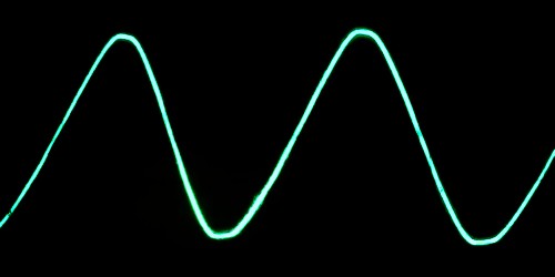
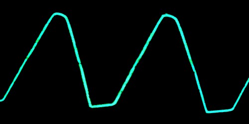
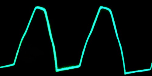
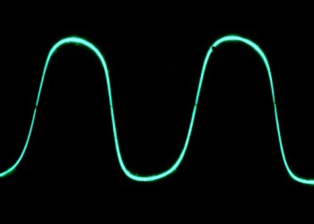
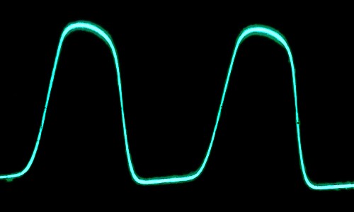
Output into 16 ohms...
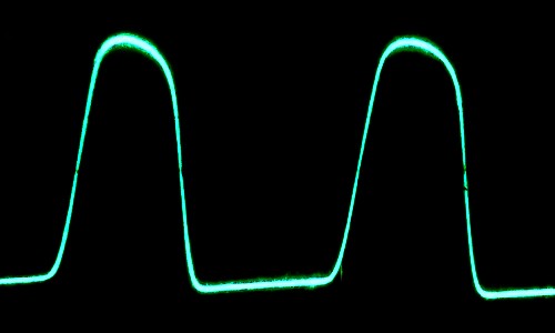
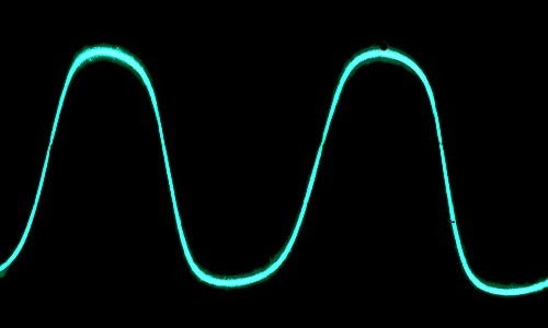
Output using the master volume...
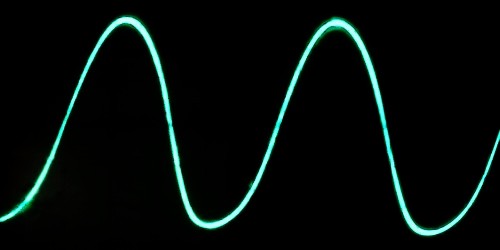
Scoping the output of V2A at the master volume hot terminal...


6/23/25 - The frequency distortion at the top of the waveform in
the last two plots appears to be caused the response of my scope
probe in the x10 position, it does not appear in the plots taken
from the amplifier output.
6/25/25 - Voltage readings with different preamp tubes...
Line = 113.7VAC   Philips           JJ                V1=JJ V2=EH
-----------------------------------------------------------------------
B+ "A"          | 341V            | 341V            | 341V            |
B+ "B"          | 296V   (9.57ma) | 295V   (9.79ma) | 295V   (9.79ma) |
B+ "C"          | 231V   (2.95ma) | 225V   (3.18ma) | 226V   (3.14ma) |
6V6 cathodes    | 18.33V (73.3ma) | 18.30V (73.2ma) | 18.32V (73.3ma) |
V1A plate       | 161.2V          | 149.1V          | 149.4V          |
V1B plate       | 160.4V          | 145.5V          | 150.2V          |
V1  cathodes    | 1.158V (1.41ma) | 1.292V (1.58ma) | 1.267V (1.55ma) |
V2A plate       | 156.8V          | 149.1V          | 147.4V          |
V2A cathode     | 1.126V (0.75ma) | 1.154V (0.77ma) | 1.196V (0.80ma) |
V2B plate       | 188.5V          | 179.5V          | 182.2V          |
V2B cathode     | 42.9V  (0.75ma) | 46.1V  (0.80ma) | 44.8V  (0.78ma) |
-----------------------------------------------------------------------
Measurements are approximate and depend on resistor tolerances,
line voltage fluctuations, meter accuracy and loading, etc. The JJ
in the last test was a different sample. As can be seen by this
chart, different brand tubes produce somewhat different readings,
even the two sections in the same tube can differ - V1A and V1B
plate voltages should be nearly equal.
Component value tweaks
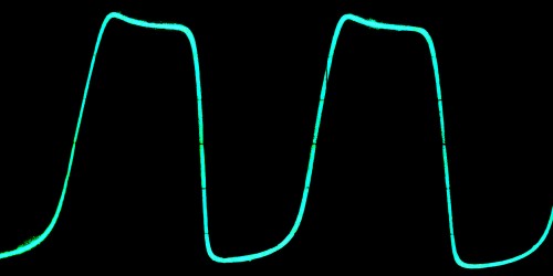
7/12/25 - Last weekend I took the amp to an outdoor jam and although it sounded ok and got the job done, it was struggling to keep up with the drums and bass and the other guitar. 9.9 watts at clip then going lopsided doesn't really cut it with a loud band. First thing is keep it from going lopsided so badly, basically replace the 1.5K 6V6 grid resistors with something much bigger. Usually I use 56K for this situation but didn't have any handy, and simulation suggested that the bottom (cathode side) grid resistor should be a bit bigger than the top (plate side) resistor to balance out the clipping, so used 33K on the top (V3) and 47K on the bottom (V4). While at it also reduced the 1.5K in the phase splitter to 1K to give it more headroom, and reduced the 1.5K cathode resistor in the V2A 2nd gain stage to 1.2K to drive that stage a bit harder and even out the initial clipping symmetry and help keep it square longer before it does the asymmetric thing.
These simple changes made a fairly significant difference. Before
it was struggling to get 9.9 watts and clipping on the bottom side
first, now it gets a nice 10.125 watts at clip hitting both sides
of the wave at the same time. It still clips a bit more on the
bottom side when pushed but it's much improved over the original
circuit, squaring both sides of the waveform rather than the
bottom side stealing power from the top side until it gets way
into clipping. The added power now comes immediately which should
improve its perceived loudness.
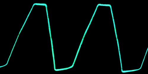
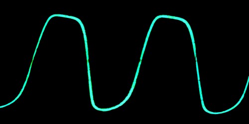
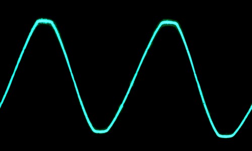
This is with the master all the way up at various levels of
clipping...

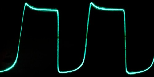
Backing off the master volume a bit keeps the clipping more even,
maximizing output power...
Preamp distortion is mostly like it was, maybe a bit more rounded
on the bottom side...

[note - I had the output transformer wired backwards so flip the
phase of all scope plots taken from the speaker output]
This should do, will find out on the next jam.
Here are the new measurements...
Idle measurements... line=117.8VAC

B+ "A"        359V
B+ "B"        309V
B+ "C"        237V
6V6 cathodes  19.4V
V1A plate     164.7V
V1B plate     163.3V
V1 cathodes   1.215V
V2A plate     153.2V
V2A cathode   1.072V
V2B plate     184.8V
V2B cathode   53.2V

Dynamic measurements... 8 ohms, MV all the way up, line=119.8VAC

           Idle        At clip     Heavy clip
B+ "A"     366V        357V        341V
B+ "B"     315V        290V        268V
B+ "C"     241V        225V        208V
6V6K       19.8V       22.5V       26.7V
OutPwr      ---        10.125W     16.3W (approx)

Derived measurements... (OT resistance 135 ohms per leg)

4.7K I     10.85ma     14.26ma     15.53ma    ("A" - "B") / 4700
4.7K D     0.553W      0.955W      1.134W     ("A" - "B") ^2 / 4700
22K I      3.36ma      2.95ma      2.73ma     ("B" - "C") / 22000
250 D      1.568W      2.025W      2.852W     6V6K ^2 / 250
6V6 K I    39.6ma      45ma        53.4ma     (6V6K / 250) / 2
6V6 SG I   3.745ma     5.655ma     6.4ma      (4.7K_I - 22K_I) / 2
6V6 P I    35.855ma    39.345ma    47ma       6V6_K_I - 6V6_SG_I
6V6 SGK V  293.44V     264.84V     238.29V    B+B - 6V6K - (6V6_SG_I * 470)
6V6 PK V   341.36V     329.19V     307.09V    B+A - 6V6K - (6V6_P_I * 135)
6V6 SG D   1.1W        1.5W        1.53W      6V6_SG_I * 6V6_SGK_V
6V6 P+L D  12.24W      12.95W      14.43W     6V6_P_I * 6V6_PK_V (inc. load)
6V6 P D    12.24W      7.89W       6.28W      6V6_P+L_D - (OutPwr / 2)
These are approximate calculations and do not take into account
component tolerances, tube imbalance, transformer losses, meter
inaccuracies etc. At first I was calculating rather high plate
dissipations at and beyond clip until I realized that the number
also included the power delivered to the load, after subtracting
that it looks like plate dissipation is the highest at idle. Not
sure if it's totally right but the math seems valid, basically
calculating plate input power minus output power, whatever is left
is the plate dissipation. The heavy clip figure is suspect since
the meter I used is not true-RMS, the voltage reading it gives for
a near square wave is probably not that accurate.
I considered possibly adding a rectifier bypass switch to
increase the power output, but after simulating and calculating to
make that safe(ish) would require increasing the 6V6 cathode
resistor to about 330 ohms and inserting another 330 ohms in
series with the diode supply, just to get it to about 15 watts at
clip. Problem is the increased cathode resistor makes it bias too
cold in the normal rectifier position, would have to use a double
pole switch to avoid that. Maybe but it's already running near the
14 watts max 6V6 plate dissipation so have to be really careful.
Something like that would be better applied to a fixed bias output
section so the idle current can be controlled.
A simpler solution for increasing output power is find a
better-matching output transformer. With the W041318 transformer
supplied with the kit I get more power into 16 ohms (around 14
watts) than into 8 ohms (around 10 watts). Seems that a 6600 ohm
primary is too low, many of the 5E3 replacement transformers are
in the 8000 to 8500 ohm range. A cheap alternative is the 8000 ohm
to 8 ohm P-TGO-002 from Antique Electronics Supply, only $30 plus
shipping. The Hammond P-T1751M looks nice, 8000 ohm primary and
4/8/16 ohm secondary [$54 plus shipping].
8/17/25 - Installed the P-T1751M transformer, that boosted the
output power at clip into 8 ohms to over 12 watts, peak power is
about 18 watts with the master backed off a bit. Not sure (my ears
have been funny lately) but it seems to have a bit more highs now.
Note that the phase of the P-T1751M transformer is the opposite
from the supplied W041318 transformer and most other (but not all)
transformers with brown/red/blue primaries, so for the same
phasing the blue and brown wires need to be reversed. Not sure
what the correct phasing even is for the 5E3 circuit - with no
negative feedback it doesn't matter unless paring with another
5E3. I went by the Weber layout guide which had the blue connected
to V3, so used brown on V3 with the 1751M to keep the same phase.
Then discovered the Weber schematic shows the opposite phase as
the layout so need more research to see which is correct.
Looking at the various kits there seems to be a preference for
brown on V3 with normally-phased transformers so I think mine is
actually wired backwards. The P-TGO-002 transformer is
specifically made as a 5E3 drop-in replacement, and it's phased
with the dots on primary green and secondary black, and the
original 5E3 schematic shows green on V3. So with the 1751M that
would be blue on V3 so yeah it's backwards from the original
circuit - reversed the wires (again). With a single amplifier it
really doesn't matter and it's still basically 50/50 chance of
phasing correctly with another random amp, but at least if I pair
it with another 5E3 it's more likely to match. Maybe.
Another thing I learned... Amplified Parts and Antique Electronic Supply
are basically the same company - same parts and part numbers, same
prices, same address, both are the public version of CE Distribution.
8/21/25 - After examining a few more 5E3 amp kits and builds
there seemed to be a preference for brown on V3, which would be
blue on V3 using a backwards-phased Hammond transformer, but
really there is only one way to settle the issue - do a negative
feedback mod! With negative feedback applied to the cathode of V2A
in the 5E3 circuit there can be only one correct connection, which
as it turns out is brown on V3 with a transformer phased with dots
on brown and black, the consensus for most of the kits and the way
I currently have it wired. But as always when replacing an output
transformer always fire it up at first with the negative feedback
disconnected to make sure that connecting the loop decreases the
gain.
For my negative feedback mod I used the existing DPDT center off
switch I already had in place and modified the wiring so that the
100K post control load remained unchanged (no feedback, this is
the setting I use the most), the center position is the stock
front end with negative feedback, and the far position, previously
the 39K preamp loads, is now stock. This way I can directly
compare the effect of the negative feedback without switching any
other circuit elements. I never used the 39K load position anyway,
was intended to reduce the gain and avoid blocking distortion but
the 100K post control load does that better.
The gain switch is now wired like this...
                               O--O---.  stock
      ground-------------------O--O   |  stock with negative feedback
      V2A grid---------100K----O  O   |  post-control loading (no NFB)
    (control outs)                |x  |
      V2A cathode--------+22uF----*---'  For negative feedback also on the loading
    (and cathode R)               |      position break the connection marked "x"
      speaker-------------39K-----'
The 22uF is the same part that was across the V2A cathode
resistor, the only added part is the 39K NF resistor. When the
switch is in the 100K post control load position it grounds the
22uF cap and also grounds the negative feedback signal, so the amp
operates without negative feedback, with only the 100K resistor
loading the output of the control network. Which doesn't reduce
the available gain all that much, mainly just smooths out the
control taper to make it easier to get cleaner tones. When the
switch is in the center off position then the front end is stock
but negative feedback is applied through the 22uF capacitor. The
stock position grounds the cap removing the negative feedback
signal, restoring the stock preamp circuit.
Did some more testing in the shop and found that the NOS tube I
had in V2 was getting flaky, although it was working it was
fooling me with its waveforms, changing the V2A cathode resistor
to 1.2K was a tweak in response to a bad tube! Replaced the old
12AX7's with JJ ECC83S and changed the cathode resistor back to
1.5K, now the plots look normal again. I did verify with a
clipped-on control pot that lowering the cathode resistance below
1.5K made the clipping response worse, so 1.5K it is. But sticking
with the 1K cathode resistor value for the phase inverter.
. . . . . . . . . .
At some point I probably should clean up this section, a lot of
the above no longer applies to this amp - the 39K first stage load
mod is no longer present, was an attempt to solve the "farting
out" problem, which it sort of did but other methods ended up
working better in practice and I found myself never using the 39K
switch position, plus those (unused) resistors hanging in the air
over the fiberboard were starting to bug me, so when the negative
feedback mod came along they had to go. Of all the mods I've made,
the ones I like the best are coupling the channels using a 1000pF
capacitor, the master volume, the 100K post-control load mod for
better control taper and blending, and increasing the values of
the 6V6 grid stop resistors to keep the phase inverter from
crapping out. For cleaner tones and stage work the negative
feedback mod might become a new favorite - actually I've never
heard the amp sound that clean. I'm using a fairly high amount of
feedback (39K) and it drops the gain considerably, making the
otherwise stock preamp setup quite usable (the stock preamp clips
if the controls are much over about 2 making it hard to do
anything clean). It also noticeably affects the preamp clipping
characteristics when using the master volume, as the V2A clip
stage is within the negative feedback loop.
Here is an updated schematic showing the changes I have made so
far...

Voltage readings with AC line = 122.7V (a tad high) with JJ 12AX7
(ECC83S) and EH 6V6 tubes...
                  Idle     13.03W   15.58W   16.86W   21.06W
                  ------   ------   ------   ------   ------
main supply       375V     366V     363V     359V     352V
SG supply         322V     295V     292V     288V     277V
"C" supply        242V     227V     227V     223V     216V
6V6 cathodes      20.4V    23.3V    24.4V    25.1V    27.1V
V1A plate         156.6V
V1B plate         158.8V
V1  cathodes      1.413V   (preamp voltages not
V2A plate         154.6V    measured under load)
V2A cathode       1.367V
V2B plate         186.1V
V2B cathode       57.7V
The 13.03W figures are for just slightly into clip into 8.4 ohms,
the estimated resistance of my dummy load and connecting cable.
The remaining measurements are for various degrees of clipping up
to almost square-wave. Power figures are estimates based on the
numbers my non-RMS meter gave me, which are probably
super-accurate but should be in the ballpark.
Derived measurements... (approximate, component tolerance and
load sharing are not considered)
                  Idle     13.03W   15.58W   16.86W   21.06W
                  ------   ------   ------   ------   ------
4.7K 2W diss.     0.60W    1.07W    1.07W    1.07W    1.20W
250 5W diss.      1.66W    2.17W    2.38W    2.52W    2.94W
Total 6V6 curr.   81.6ma   92.0ma   97.6ma   100.4ma  108.4ma
Preamp current    3.64ma   3.09ma   2.95ma   2.95ma   2.77ma
6V6 SG current    3.82ma   6.01ma   6.08ma   6.08ma   6.59ma  (per tube)
6V6 plate curr.   37.0ma   40.6ma   42.8ma   44.1ma   54.2ma  (per tube)
6V6 SG diss.      1.223W   1.756W   1.758W   1.734W   1.805W  (per tube)
6V6 plate diss.   13.12W   7.399W   6.702W   6.295W   7.080W  (per tube)
The formula I used to calculate plate dissipation is...
((main_supply_V - 6V6_cathode_V - (6V6_plate_current /
150)) * 6V6_plate_current) - (output_power / 2)
...the 150 figure is the output transformer leg resistance.
Basically it calculates the plate input power then subtracts half
of the output power to estimate the actual plate dissipation.
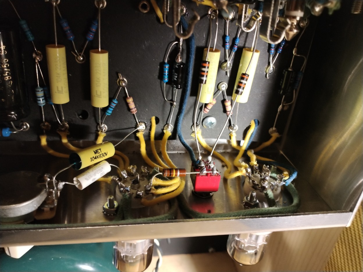
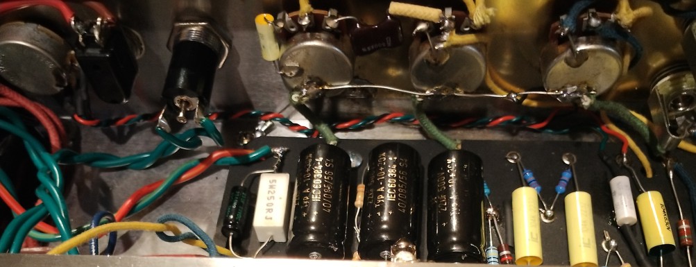
Here are some new pictures of the internals...


The 68K jack resistors are in the air rather than on the
fiberboard is to prevent leakage from the nearby high voltage
eyelets, especially in humid environments, putting a fraction of a
volt on the input lines depending on the impedance of whatever
their hooked to. While that's not enough to seriously affect
performance, it caused pops when plugging stuff in and out and
operating pedal footswitches.
I didn't twist the heater wiring, instead cut each wire to length
then tightly fitted them under the lip of the chassis. This seems
to work fine, the amp is very quiet. For grounding I used a wire
on the back of the controls that's also grounded to the input
jacks, with the supply side of the wire grounded to the chassis.
Probably overkill but I hate it when nuts get loose and bad things
happen. The circuit grounds ground to the control ground wire, and
the V1 cathode R/C grounds directly to the input jacks. The
transformer center-tap grounds to the first filter cap ground on
the fiberboard (actually the 6V6 cathode resistor but same effect)
to make sure no supply ripple current passes through the chassis
or other ground networks. The only place I trusted a control
ground was the master volume but it's a nice CTS control placed
underneath the amp and unlikely to come loose. The reason it's
underneath is because I wanted to preserve the stock look but also
so that when using as backline for jams I wanted to be able to set
the maximum volume in a way that's less likely to be messed with
by the jammers... sometimes 15 watts is still too loud.
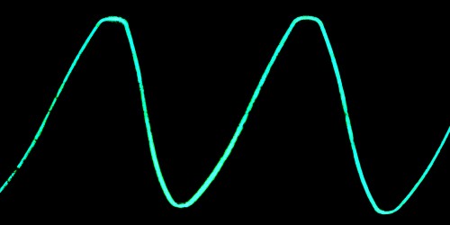
Scope plots... These are with JJ ECC83S preamp tubes and EH
6V6's.
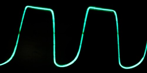
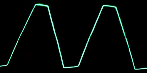
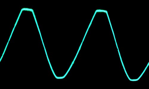
Output with the stock setting (no negative feedback), delivering
~13W, ~15.6W, ~16.9W and ~21.1W...


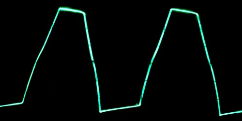
Output with the negative feedback setting, delivering ~13.9W and
~15.5W...


The at-clip plot is noticeably cleaner and it's more symmetrical
going into clipping. The higher power plots are almost identical
to the non-feedback plots so omitted.
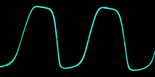
Preamp distortion with the negative feedback setting, 130mV input
into bright #1, normal volume down. Delivering ~7W, ~8W, ~9.1W and
~10.5W as the bright volume set to 3, 4, 8 and 11...


Preamp distortion with the 100K load taper mod setting, 130mV
input into Normal #1. Delivering ~6.3W, ~7.7W, ~9.2W and ~11.6W as
both the normal and bright volumes are set to 3, 5, 8 and 10.5...


Preamp distortion with negative feedback enabled starts off more
symmetrical but flattens out on the bottom sooner with sharper
edges. Distortion without negative feedback (the waveforms with
the stock setting are similar) is mushier, starts out more rounded
on the top and stays rounded on the bottom longer before
flattening out. Both produce extreme duty cycle shift when pushed
must past grid conduction, an extra grid stop resistor on V2B
could help avoid this but I kind of like it. Plus this design
isn't meant for heavy overdrive anyway, but it is desirable that
it tolerate a certain level of overdrive without crapping out to
make it pedal-friendly.
10/2/25 - I did a little thing to my amp...
I added three 1N4148-type diodes in series with an old 6.8K
resistor across the 100K load mod resistor with the cathodes to
the grid, so that it's switched into the circuit when the mod
switch is in the load position. What a difference! Before I
couldn't get the volume(s) much past 70 or 80 percent without it
getting gnarly-sounding - a little bit of nastiness is fine but as
can be seen in the last scope photo above, it got basically
unusable. Needs to stay more like the previous photo even when all
the way up. When one has an amp with knobs that goes to 12 (which
is one more than 11) I want to use it, otherwise I can't really
say my amp goes to 12. Now it does! I can even turn all three
knobs to 12 at the same time and it stays tight with hardly no
blocking distortion (but it sounds a bit better if the normal is
backed off a bit to lose some of the low end drive). Previously
this just wasn't possible with this amp, it's now got a character
about it that I haven't heard before from this amp. Or most amps
for that matter.
One of the things I like about the 5E3 design is it's so simple
and honest, it's almost like being wired directly to the speakers.
There's hardly any tone shaping besides the tone control, and in
the case of this modded version the 1000pF cap coupling the normal
channel to the bright channel. Most of the mods I've made to the
design were mostly out of necessity so that I could use it, but
trying not to erase what makes the 5E3 what it is. Just things
like adding the master volume because I have neighbors and I still
need to turn it down at jams, adding the 100K load resistor to the
output of the control network so I could actually use the
controls, increasing the 6V6 grid-stop resistors because that gets
done with every cathodyne-based amp I have to play with to keep it
from sounding like crap when it clips. This mod feels a bit
different, it's like I turned it into something else entirely
using solid state components to actively shape the waveform. At
least it's only in the load mod position (actually it has to be as
it's incompatible with the grid signal level required by the
negative feedback mod). And the amp still has a stock(ish)
position, although I never use that setting. But I'm over it, if
it takes diodes to make my vintage-style amp more usable then so
be it.
In the original 5E3 design, even with the added 100K grid load,
at higher volume settings (close to maximum) when the grid
conducts too much it charges up the coupling caps more negatively,
which drives the tube more and more into cutoff. Usually the fix
for that is to put a large resistor in series with the grid so
that it can't charge the caps up enough to cause trouble, but I
don't want to do that because the miller effect would rob the
highs and it ain't got much of that to begin with.. amps that use
that technique usually have another frequency-shaping network
preceding it, or are channel-switching amps with a separate clean
channel and it doesn't matter. The diodes fixes it in another way,
they limit how negative the grid can go thus avoiding the problem.
In times past when I did similar tricks I would usually use a
diode in series with a zener so that it only kicked in well after
clipping and only to improve symmetry and keep it from going wonky
to one side (which in the case of Marshalls can blow the output
tubes), but for this amp with a low-value plate resistor (compared
to what I'm used to) and running from a fairly low supply voltage,
I just didn't like the way the cold side clipped. So for this, the
diodes start conducting roughly about the same time the grid
starts conducting in the other direction. The resistor in series
with the diode string makes it respond similar to (but not the
same as) how the grid responds, even though the diodes are
clamping the voltage the resistor preserves the dynamics so that
even under fairly heavy clipping an increase in signal still
causes an increase in the output level. That was the old Tube
Screamer trick and used in countless other overdrive pedals to get
a more tube-like tone.
So whatever, I just put the equivalent of half of a tube screamer
in my 5E3 using bench scrapings, and I like it. I was relieved to
discover that the 1N914 diode (essentially the same thing as a
1N4148) is not a modern part at all, it was first introduced in
1960 (!). Slightly after the 5E3 era but plenty early enough where
people fed up with their amp farting at high volume settings when
they played rock and roll through it could have easily done this
same mod. Or had parents, the master volume mod I did is pretty
obvious.. same with the load mod, that's just basic electronics.
There's no telling what they were doing to their amps back then,
most of it is lost to history and just speculation but it
certainly was possible.
10/7/25 - I took some scope photos with the diode mod in place...
Awesome! These shots were made with the internal temperature of
the amp at about 50C in the vicinity of the diodes (which are
temperature sensitive). There is a slight impact to the clean
tone, slightly rounded output on the cold side of V2A (which is at
the bottom of the output waveform) but in my case it compensated
for my slightly mismatched 6V6 tubes and made the clipping more
symmetrical. The preamp distortion waveform in the 2nd pane is
almost exactly as predicted by simulation.
Here is a recorded sample
with the bright volume and tone almost all the way up, normal
volume down a bit and the master volume set to bedroom level
(there are pick sounds in the background). First part is just the
amp, then I switched on my phase shifter, overdrive and delay
pedals with the same amp settings. Recorder was in the back of the
amp, there's no after-processing other than normalizing. Usually I
don't use this much amp gain with pedals but I was trying to get
it to crap out - before adding the diodes I couldn't get it this
hot before too much unpleasantness crept in. Here is another recorded sample, still
at bedroom level. Warning - it's long and rambling.
I made a non-circuit change to the amp - I moved the master
volume from underneath next to the speaker jack to the top panel
where the fuse was, which was relocated to an in-line fuse holder
inside the amp. I always hated having the fuse on the top panel,
just asking to lose the cap or worse. Much better now, was hard to
adjust the volume setting when it was underneath the amp.
I put the 0.1uF cap from the plate of V2A across the fiberboard
where the stock amp's 0.022uF was originally placed, the jumper
from the other side to V2B grid was not wired when building. I
used twisted red green and black solid-core wire to connect to the
master volume control, shielded wiring was not needed. The wires
from the MV control were routed against the chassis with red
(control hot) connected to the 0.1uF plate cap, black (control
cold) grounded at the controls, and green (control wiper)
heatshrinked to the 0.022uF cap going to V2B grid. The 0.022uF was
secured next to the 0.1uF with a bit of glue. Like this...
The other side of the 0.022uF cap is wired directly to the grid
of V2B using a bit of cloth-covered wire.
No plans to move the mod switch, it's not something I'd want on
the top anyway, flipping that switch causes huge volume changes. I
rarely change the mod switch setting anyway, it's almost always in
the "load" position that switches a 100K resistor from V2A grid to
ground, and now the diode/resistor string that fixes the preamp
overdrive tone at higher gain settings. It is easy to access if I
need something different.
12/19/25 - Over the last couple of months I've played around with
the amp, and while the load mod with the smoothing diodes is still
my favorite setting, lately I've been experimenting more with the
stock preamp setting, with just the master volume and the channel
couple/low-cut mods. Running at high gain in the stock position
requires certain picking and other techniques to avoid severe
blocking distortion, it kind of works with my pedal setup but I'd
like to have a setting that spits the difference in "angry-ness"
between the load/diodes mod and stock. I never could use the
negative feedback mod setting, sure it was clean but it caused too
much gain loss and at lower MV settings what distortion it had was
too brittle.
At first I was going to remove the NF mod and use the switch to
select a second lesser-load position without diodes, but got to
fooling around with LTspice and come up with a very much improved
way to implement negative feedback in a way that doesn't
drastically drop the gain. The gain is reduced only by the amount
of feedback applied rather than starting with an already low gain
unbypassed 1.5K then dropping it from there, the new circuit is
more like the NF method used by the later Princeton circuit. I'm
using 39 ohm and 1.5K resistors for applying the negative
feedback, a bit more than with the Princeton's 47 ohm and 2.7K
resistors.
This method is MUCH better! Because V2A's cathode resistor
remains bypassed it still sounds good when overdriven, and because
V2A gain remains maximized (at least when the MV is up) it is more
effective at correcting output stage distortion. With most of the
gain and tone restored, I could add an intermediate load resistor
(I chose 180K because it was handy) to improve control taper and
tone down at least some of the blocking distortion. When the MV is
at lower settings there isn't much gain reduction so the new NF
position is now the extra setting I was looking for. Another
advantage of the new switch wiring is stock is now the center-off
position so it doesn't depend on switch contacts - if the contacts
go bad it reverts to stock rather than to the low gain NF setting
I never used. The 39 ohm bottom-side NF resistor remains in the
circuit all the time, even in the stock position, but the effect
is negligible due to the low resistor value. Other values can be
used, I used 1.5K/39 ohm resistors because they were handy,
providing a FB ratio of about 38:1. This is a bit more FB than the
Princeton's 57:1 ratio, change the 39 ohm to 27 ohm for that.
Here's the new schematic...
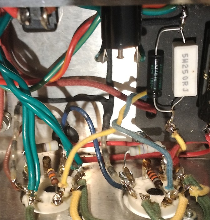
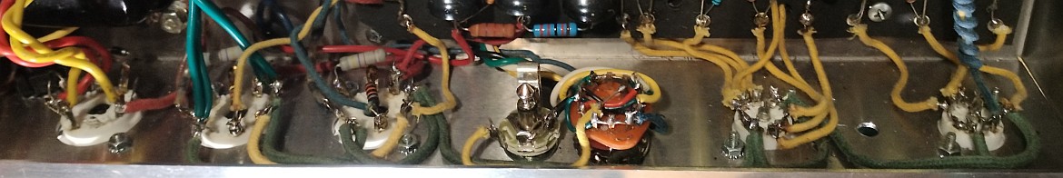
I need to take new pictures of the innards for updating docs and
stuff, for now this shows the new mod switch wiring...
More circuit details below in the simulation section.
12/21/25 - Flyback Diode Mod
While playing around with a new simulated speaker model I made a
somewhat horrifying discovery - under heavy power amp clipping
voltage spikes on the output transformer primary can reach 1.2KV
or more, and dip several hundred volts below ground potential.
Yikes! This is under simulation but I have no doubt this actually
happens. I used to think they were only needed to protect against
an open speaker load but after playing around with the speaker
simulation I'm now of the opinion that they should always be used,
just make sure they're rated for 3KV or more.
The reason is because a speaker is inductive and its impedance
rises as the frequency increases. The impedance also dramatically
increases at the speaker's resonant frequency, usually in the
vicinity of the low E note on a guitar. The spikes appear because
at certain frequencies the amp is basically operating without a
load! Another related reason is inductors store energy, when the
signal suddenly stops or reverses direction, the inductance of the
speaker tries to dump that energy back into the amplifier. Solid
state amps don't have the open load issue but they also usually
include flyback diodes to absorb the back-voltage from the speaker
and keep the the output signal between the rails. The output level
of a tube amp usually increases as the load impedance increases,
which is not necessarily a bad thing because that compensates for
the high frequency loss caused by the speaker inductance, but
there has to be limits or things eventually start randomly blowing
up. The flyback diodes pretty much solve the problem by clamping
the plate so it can't go below ground, which because it's a
transformer, also limit the maximum voltage on the other side of
the output transformer. With the diodes in place the plate voltage
is limited to around 800 volts peak.
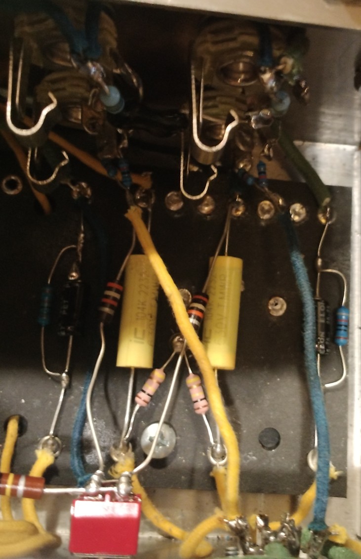
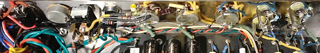
To do the mod I used three 1N4007 (1KV) diodes in series for each
6V6 tube plate, obviously the cathodes must face the plates.
Returning the anodes to the 6V6 cathodes would work but by my
figuring grounding the anodes is better. Here's the mod in
place...
There is some debate on the internet about flyback diodes,
complaints include they are unreliable, they degrade over time,
and they change the tone of the amp. The first two are sometimes
true as some makers used under-rated diodes and they would
eventually blow as the spikes add up and do damage. I've replaced
my share in the shop but they were always under-rated to begin
with. Now that I think about it, I've replaced many more output
transformers and usually the amps they were in did not have
flyback diodes. As far as changing the tone of the amp, that one
is true, at least to a slight degree and depending on what the
musician wants. It is said they reduce the "fizz" and dull the
high frequency response. Yes I can see it in the simulations, the
diodes reduce the amplitude of the high frequency spikes. I can't
hear it in the simulation output but there is a very slight
difference.
(this probably should be in the simulation section but including
it here because it relates to the merits of this mod)
Here is the simulated output with the flyback diodes,
and without the flyback
diodes. The simulation was set with both volumes at 90%, the
tone at 80%, the master volume at 100%, the mod switch in the
load/diodes position, and using a model of a Lil' Texas speaker.
Don't mind the lick but I use that input file with all these
simulations so I can make better comparisons (it's in the 5E3mod simulations archive).
Full samples...

Zoomed in...

Not seeing anything beyond single-pixel plotting differences.
There is a significant difference when looking at the raw output
but frequencies that high generally don't make it out of the
speaker.
Here are the FFT spectrums with and without the diodes...
No wonder I couldn't hear any difference, looks like the diodes reduce 8khz output by about half a db and 16khz by about 1db, not to mention trying to hear sub-db differences that are 25-40db below the main frequencies. Also, I really don't want to hear "fizz" or much of anything over 8Khz in my guitar sound unless I'm playing clean, so if the diodes take out some of that when clipping the amp then I consider that a good thing. The diodes don't conduct unless the amp is clipping, so the tone with pedals and preamp distortion is not affected at all. This is a simulation using imperfect models with its output converted to MP3, so real life performance is going to be different, but here I'm only trying to compare the difference with and without flyback diodes and not the difference between a real and a simulated amp, which is a lot.
While researching this I came across a post about a DAW amp
plugin that had a "switch" for the flyback diodes, claiming a
significant difference. I wonder how the speaker was modeled - if
modeled using a frequency-dependent impedance with the signal
taken from the amp output and run through a filter to match the
speaker's frequency response, then there's going to be a big
difference with and without the diodes, on the order of several
db. Not saying that's what's going on but such a setup goes
against how speakers work. The spikes come from energy that
couldn't make it through the inductance of the voice coil, so if
you can hear that out of the speaker to a significant degree then
you've got some serious distributed capacitance in the voice coil
or there's something else connected to the amp output like a DI or
tweeter. I'll change my mind if there is any real evidence to the
contrary but from everything I can tell it's better to have
properly-rated flyback diodes to protect the transformer from
those spikes. Or worse, a disconnected speaker.
That all said, the tone of the amp and speaker combination at
least to a degree depends on the amp output voltage increasing in
response to the rising impedance of the speaker, extending the
high frequency response beyond what it would have with a low
impedance source. However in my opinion the effect from adding
flyback diodes is very subtle, other things (like turning the
knobs) have a much larger effect. The only reason I spent this
much time on this was because I wanted to make an honest
assessment about this flyback thing.. I learned stuff.
1/4/26 - Now that the negative feedback mod setting works without
the huge volume shift of the previous version, I dug around in the
back room and found an antique but heavy-duty DPDT center-off
toggle switch - NOS from the '70's. As expected after close to 50
years in its bag the contacts were totally open on the meter but
after cleaning with mineral-based electronics lubricant it came
back nicely and showed no signs of flakiness. So removed the
standby switch (which I didn't really use), moved the power switch
to the end, and bolted the new mod switch in its place. An earlier
concern was it might pick up noise from being closer to the power
section but after moving the circuitry to the top I was pleased
that there was no noise pickup at all, even in the stock position
with both volumes down where the impedance of that node is about
500K. I did however discovered that the bright channel picked up a
bit of hum when its volume was wide open, which was cured with
some foil on the back panel. Other than removing the standby
switch there was no circuit changes.
New pictures...
New version of the schematic...
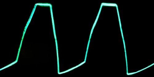
The 6V6's have aged a bit since the last time I made scope shots,
also I've been running it with the old Philips 12AX7's, so the
waves are a bit different now. Previously in stock mode I was
getting a bit of off-centered clipping and using the load mod with
the diodes actually brought it back to symmetrical but now it's
the other way around. Here are at-clipping scope shots for stock,
NFB and load/diodes...
Preamp distortion in the stock position...
Preamp distortion in the load/diodes position...
Not much has changed but in the load position it seems to be
getting into the diodes a bit more than before, possibly because
I'm using the Philips tubes now rather than the JJ's. Another
possible factor is now the diodes are sitting over the heat from
the power tubes so get a bit warmer causing a bit more conduction,
I measured about 55C versus 50C between the preamp tubes, but the
difference is probably mostly from different tubes.
This little UTF-converted ASCII schematic summarizes most of the
tone-affecting parts of this mod...
The other main tone-affecting mod is using a 1000pF capacitor to
couple the normal channel into the bright channel's #1 jack switch
to provide a low-frequency rolloff to reduce blocking distortion.
LTspice Simulation of the modified
5E3 circuit
6/20/25 - To get a better idea of what's going on with this
circuit I entered it into LTspice.. and discovered that the Duncan
12AX7 model I was using barely functioned with this circuit, with
a 1.5K cathode resistor and a 100K load resistor it clipped only
on the top side, clearly not right. That's when I found myself
going down a rabbit hole of trying various tube models.
The one that best matched the voltages I measured in the actual
circuit was a 12AX7 model labeled "NEW MODEL", obtained from https://www.normankoren.com/Audio/Spice_preamp_2.html.
Other models that worked reasonably well are the 12AX7A-mz model
from https://www.diyaudio.com/community/attachments/tubes-ltspice-lib-txt.999666/,
the JD_12AX7 model copied from an
Electronic Design article (was in an image so typed it in
without the comments), and the 12AX7CRV Model Paint example from https://www.dmitrynizh.com/tubeparams_image.htm.
I found two 6V6 models that mostly worked: the Duncan
6V6 model which better matched the bias voltage in the real
circuit (the original has typos, fixed in this sim), and a 6V6GT
model from Ice
Amplifiers that biases a bit higher and has lower screen
grid current when overloaded. [...previous simulations replaced
with improved simulations that better match what I'm seeing on the
scope]
6/23/25 - The 12AX7 models I found tended to be a bit too rounded
on the bottom part of the waveform, the grid diode is too soft. So
I used the Model
Paint program to make my own 12AX7MP model based on a 12AX7
datasheet from Automatica then manually tweaked the advanced
grid parameters until the waveform looked approximately like the
real thing (although that made the resulting grid current at
higher positive grid voltages unrealistic). Still not exact but
closer, and like the other 12AX7 models besides the "NEW MODEL"
the resulting plate voltages are a bit lower than measured in the
actual circuit. The plate resistance seems to be a bit higher, so
in the 5E3 circuit the 12AX7MP model clips on the top first, which
better matches what I normally see with a 100K/1.5K 12AX7 preamp
stage. I got lucky with the mostly symmetrical clipping of the
Philips 12AX7 I have in the amp.
The simulations are approximate. The output transformer is simply
coupled inductors and doesn't model the response of a real output
transformer. Then again I'm of the opinion if you can "hear" the
output transformer it's probably too small. The power supply in
this simulation is just a voltage source in series with a
resistor, the sag is somewhat similar to the real circuit but the
real amp sags a bit more.
Power tube clipping of various degrees, master volume is all the
way up... (click images to make bigger)

Typical nastiness of a single-triode phase inverter - when the
bottom tube grid conducts it messes up the top tube drive. The
effect is somewhat worse in the actual circuit.
Here's the cool thing, backing off of the master still permits
full power output but with much less nastiness...

Preamp distortion...

This looks similar to the waveform of the real thing but I might
have got the grid conduction too hard, the parameter "IGEX" in the
12AX7MP model controls how quickly the grid conducts, I currently
have it at a fairly high value of 15, lower values result in
softer clipping on the bottom part of the waveform.
Here's the same plot with the Koren "NEW MODEL" 12AX7...
It's pretty close but to me it seems like it has a bit too much
rounding on the bottom of the waveform, more noticeable on the
green V2A plate trace. But maybe not... this model more closely
matches the DC values in the real amp. Getting grid conduction
right is tricky, in addition to modelling the forward conduction
characteristics there also seems to be some sort of hysteresis or
memory effect - the onset of conduction is harder than the
release. This is tricky to model with spice and none of these
models take that into effect (a rabbit hole for another day).
Simulated preamp distortion with a guitar signal... (output in 5E3mod_9863.mp3)

Simulated power tube distortion with a guitar signal (output in 5E3mod_5568.mp3)
Here is a zip file containing the 5E3mod
LTspice simulation files.
At first I thought the simulation wasn't capturing the typical
asymmetric clipping of a 5E3/Princeton style output stage, but
that was mainly because I wasn't turning the master volume up
enough to make the 6V6's conduct. It still isn't a perfect
simulation (with the real circuit the bottom side starts squashing
as soon as the top side clips) but the effect is there. The master
volume makes a huge difference in taming the single-triode phase
inverter. Another trick that helps prevent uneven squashing is
increase the size of the 6V6 grid stop resistors, they're 1.5K in
the stock circuit but they can be increased to 56K or even 100K to
avoid excessively loading the phase inverter when the grids start
conducting.
7/4/25 - More simulation stuff...
The previous simulation used 900 ohms in series with the supply
voltage, but the sag still wasn't realistic - to approximate what
I was actually measuring I had to increase the resistance to 2K,
which seems a bit unrealistic. So I made another simulation using
a Duncan 5Y3 tube model and transformer models inferred from
datasheets and actual voltage and resistance readings... I still
had to twiddle the sim using series resistance but now only needed
50 ohms to fairly closely match what I was measuring from the real
circuit.
For the output transformer I found the Weber datasheet for the
W041318 and found it was 6600 ohms CT to 8 (I probably should have
known that) so the henry ratios are (6600/4) 1650/8 so for 100
henry primary legs the secondary needs to be 0.485 henries.
Primary resistances were set to what I measured, 135 ohms for the
blue winding and 139 ohms for the brown. Secondary resistance was
set to 0.3 ohms to sort of match the output power I was getting -
9.9 watts at clip into 8 ohms. For the W025130 power transformer,
with 118.4VAC line I measured 356V per leg, primary resistance
(including fuse and wiring) was 2.8 ohms, one HT leg was 72 ohms
and the other was 76 ohms. The henry ratio is 356/118.4 squared =
~9.04 so for a 10 henry primary each secondary leg needs to be
90.4 henries. For simulation purposes the exact henries doesn't
really matter as with perfect coupling there is no leakage
inductance, only the ratios matter.
From the actual amp with 121.3VAC line (I get a lot of variation
here), at idle "A" is 369V, "B" is 319V and "C" is 248V. At clip,
"A" is 357V, "B" is 291V and "C" is 227V. In heavy clip, "A" is
343V, "B" is 271V and "C" is 213. With the new sim, at idle "A" is
369V, "B" is 320V and "C" is 251V. At clip "A" is 359V, "B" is
301V and "C" is 236V. With heavy clip "A" is 347V, "B" is 281V and
"C" is 216V. It's not exact but it's fairly close to the actual
readings, the main discrepancy is the Duncan 6V6 model doesn't
draw as much screen grid current under overload conditions as
6V6EH tubes in the amp.
Here's the plots with light and heavy clipping...

That's a lot of ripple on the "A" supply. New LTspice asc/plt
files added to the zip file.
Simulations using the tweaked resistor values
7/13/25 - I tweaked some of the resistor values to improve the clipping performance of the output stage. The 6V6 grid resistors were changed from 1.5K to 33K on V3 and 47K on V4, this lessens the load on the phase splitter so that the clipping is more even rather than mostly concentrated on one side. The 1.5K in the phase splitter (V2B) was reduced to 1K for more headroom, and the 1.5K cathode resistor in the 2nd stage (V2A) was reduced to 1.2K to make it clip a bit more on the bottom first before going flatline on the top.
At clipping...


Moderate clipping...

Heavy clipping...


The 6600:8 transformer that came with the kit doesn't seem to be
the optimum match for this amp (I get more power at 16 ohms than
8), considering replacing it with a Hammond P-T1751M 8000CT
to 4/8/16 to get a bit more clean power. After the resistor mods
I'm getting about 10.2 watts at clip, according to the sim the
replacement transformer should give me 13 watts or more at clip...


New LTspice files added to the zip file.
8/17/25 - After installing the 1751M transformer I'm measuring
12.15 watts at clip into 8 ohms (118V line), not quite the 13
watts implied by the simulation but still better than the 10.2
watts from the original transformer.
9/15/25 - The last mod I did to the amp was to repurpose the mod
switch so that instead of applying 39K loads to the 1st stage
outputs it now enables a negative feedback loop using a 39K from
the speaker output to the 1.5K cathode resistor of V2A, through
the 25uF bypass capacitor since that made it easy to switch
between stock and negative feedback by grounding the junction
between the resistor and capacitor. So now the switch selects
between stock, negative feedback and 100K load mod. Reversed the
connections to the output transformer so the negative feedback
would be properly phased.
The negative feedback connection reducing the gain of the output
stage by about 8db, reducing distortion...


The effect is more pronounced with the actual amp but even with
the simulation the output is closer to a sine wave with the
harmonics reduced by about 4db. Also increased the output power to
over 13 watts at clip.
LTspice is useful for studying the circuitry, however none of the
tube models accurately capture the actual observed behavior under
clipping conditions, especially for the preamp tube models.
Actual...
Versus simulation (using the 12AX7CRV model)...


Well I guess it's kind of close I but the real thing is more
rounded when in grid saturation (bottom half of the wave from the
preamp plate but the top half of these plots due to phase
inversion of the output stage), and the models tend to clip more
on the positive/cutoff side of the wave. Adjusting the 1.5K
cathode resistor can compensate for this.
The quest for the perfect tube simulation continues....
9/16/25 - I found a 12AX7 model that works better, actually I
already had it, it's from the page Modeling
on Mondays: Nonlinear SPICE models of Vacuum-Tube Triodes (Part
3). The original model used the simple diode/resistor to
model grid current which doesn't exactly produce realistic
clipping, so put the same parameters into Model
Paint and enabled the advanced grid option, then dialed in
something that resembled the actual waveforms I was observing.
Here are the results...


That's pretty darn close. Still biasing at slightly less current
than observed but not by much. Here are the full plots...


The new 5E3mod_X3.asc file has been added to the zip file.
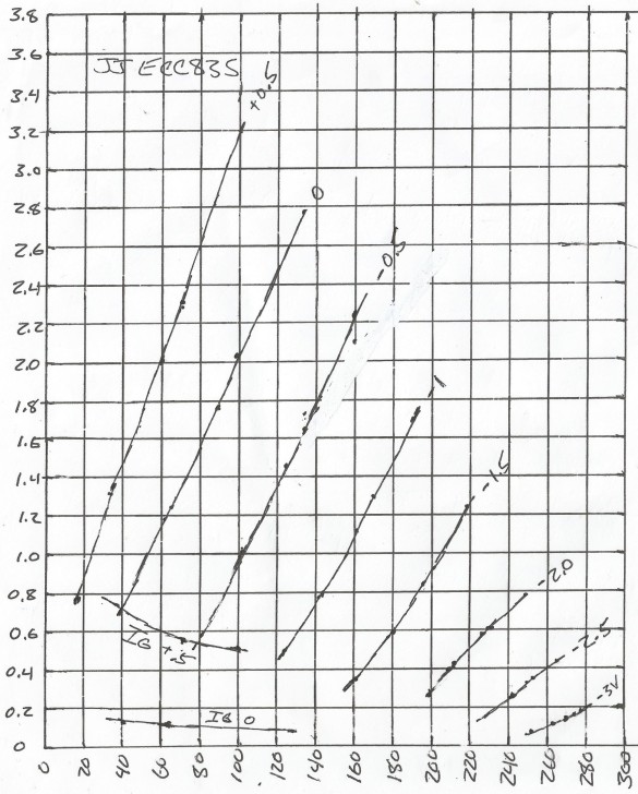
9/17/25 - The "JD" model parameters matched older 12AX7
datasheets quite well, here's the Model Paint curves with the
Mullard datasheet curves overlaid (matches other old 12AX7 curves
were similar)...
.gif)
...but not so much with the JJ ECC83S curves...
.gif)
So starting with the JD curves I twiddled the dials for a better
match...
.gif)
...and that made almost no difference. Biased at slightly less
current, maybe just a tad closer to the observed waveforms but
only by a tiny bit but it's still not replicating the real thing
which with 1.5K/100K values initially clips slightly more on the
"cold" (higher current) side. It's possible I have an off-spec
tube but at this point might need to rig up a test setup and
derive my own curves. I really don't need a full set of curves,
with a resistor-loaded amplifier for a given supply a given
current drain must result in a plate voltage defined by the
voltage drop across the plate resistor, AKA the load line.
A simple test circuit that permits measuring the grid vs plate
voltage and current for a few sizes of plate resistors centered
around 100K (say 47K, 68K, 82K, 100K, 120K, 150K and 180K or
really whatever is handy) should provide enough information to
more precisely match the model to reality. A 9V battery connected
to a potentiometer can serve as the variable grid voltage, for
each plate resistor value measure the plate voltage and voltage
across the resistor to derive the current for each grid voltage
step. Also would be a good opportunity to measure actual grid
current versus plate voltage for positive grid values.
Something like this for the test setup...
Supply V (~240V) -----RP-----*------.  vary RP around 100K
                             |      |
  (+9V for grid current)   1K 1%   V plate current
   -9V     .----------.      |      |  (volts=ma)
    |      |          |      *------*
    |    V Grid cur   |    __|__    |
   _|_     |(volts=ma)|   |_____|  Vplate
  |   |    |          |             |
  |   |<---*----1K----*----------   |
  |___|         1%    |    _____    |
    |  10K          Vgrid |     |   |
    |  pot            |   12AX7 |   |
   _|_               _|_   DUT _|_ _|_
Start with -9V on the control then for each value of RP measure
Vplate and plate current for each value of Vgrid from 0V to say 4V
stepping 0.5V (typical for datasheet curves). Then reverse the 9V
and go back to 100K plate to measure grid current at say 0.5V 1V
1.5V and 2V, noting the plate voltage for each. Seems easy enough
to set up. There are other fancy curve tester designs (such as the
various uTracer designs from www.dos4ever.com
yeah that would be nice to have) but pretty sure that just a few
measurements around the load line will be sufficient to reasonably
recreate the performance of simple 12AX7 RC-coupled amplifiers
with SPICE, especially if the positive grid current can be
accurately measured and modeled.
9/19/25 - Ok that didn't quite work out. I made up a simple test
rig similar to the above except used what I had on hand - a 250K
pot and six resistors for RP ranging from 39K to 330K (exact
values aren't important, just getting Vg/Vp/Ip datapoints).
Getting the control to settle exactly on 0.5V increments wasn't
easy (especially for positive grid voltages) but managed to record
a bunch of data which I turned into a chart...
...and used Model Paint to trace it...
.gif)
But the results were garbage...
[previous speculations as to why it didn't work removed]
9/20/25 - A couple things were going on - for whatever reason the
previous 122.7V line measurements were low, not sure why but I
suspect it was because the line voltage sagged between the time I
measured the line and took the other measurements. Either that or
the tubes aged but I kind of doubt it, more likely was just a
measurement error. The JJ ECC83S I measured has lower current than
the published specs (0.9ma at -1/150 vs 1.2ma) but otherwise works
fine, sounds good and still looks exactly the same on the scope.
The main thing though was I had the grid parameters all wrong -
was matching it at 0V and +0.5V but after reading the paper Vacuum
Tube Triode Nonlinearity as Part of The Electric Guitar Sound
which has a chart showing actual 12AX7 grid current measurements I
realized I was doing it all wrong - it's the area between -0.5V
and 0V that needs to be modeled reasonably accurately to replicate
the observed waveforms. Performance at +0.5V doesn't matter, by
then the signal is completely clamped... with a 100K source
impedance 100uA grid current is a 10V drop. Rather the region
between -0.5V and 0V needs to be modeled as an exponential rise
from about 1uA at -0.5V, about 0.2uA at -0.4V, about 4uA at -0.3V,
about 10uA at -0.2V, about 25uA at -0.1V, then increasing rapidly
past 50uA as it approaches 0V and beyond. The reason the grid
starts to conduct while still negative is related to something
they call "contact potential" which results from the welded
connections between the tube pins and elements, known as the Seebeck
Effect. Normally this isn't noticed because the two
connections for a round trip cancel each other out (unless at
different temperatures), but the grid has no return path so the
effect adds a few hundred millivolts to the effective grid
voltage, causing it to start conducting even while still a bit
negative. I think that's about right but this is all still new to
me.
The exponential function needs to be on the order of 3 or so,
when tracing the ECC83S I was using an exponent of around 1.3
while trying to match the 0V and +0.5V curves, which resulted in
harsh clipping. For the previous 12AX7JDA and other models where I
eyeballed the grid response I had an exponent of 2, which looked
about right, but in fact was robbing a bit of gain from the models
as it approached overdrive. I really should make new grid
conduction measurements focusing on the area between -0.5V to
around +0.1V, but I had some data from the previous measurements
which proved useful...
Grid V    Plate V  Grid I
-0.499V   159.1V   1.1uA
-0.502V   125.1V   1.2uA
-0.500V   101.4V   1.7uA
-0.497V   80.7V    2.1uA
-0.058V   131.6V   59.4uA
-0.064V   103.4V   64.9uA
-0.067V   92.7V    67.4uA
-0.071V   69.3V    72.5uA
-0.086V   44.8V    79.1uA
0V        127.5V   86.8uA
0V        98.6V    95.4uA
0V        61.6V    111.6uA
0V        39.0V    131.5uA
There was noise in the data - the 0V readings were +/- a couple
millivolts as it was very tricky hitting exactly 0, had to apply
positive voltage to balance out the grid current. Regardless the
drastic increase between just a little bit negative and 0 is
plainly evident, as is the effect of plate voltage. Not a lot of
data points but this data constrains -0.5V to a couple uA and
defines the slope, for the missing data used the data from the
chart in the paper, which didn't include plate voltages but
figured it was in the 100V range typical for a 12AX7 saturating a
100K load.
I didn't hit it exactly but got close...
.gif)
While at it I also tweaked the main parameters to better match my
measurement chart.
The resulting 12AX7SMP model performs quite well under
simulation...
The clipping characteristics are almost exactly what I observe on
the scope, clips more on the grid limited side first.
The simulated idle voltages match the most recent measured values
quite closely...
Node          Measured  Simulated (line=117.7VAC)
supC          237.8     237.75  (set artificially)
V1a plate     159.8     163.13
V1b plate     160.2     163.13
V2a plate     161.3     159.76
V2b plate     185.4     188.81
V2b cathode    52.3      49.81
Close enough considering resistor tolerances, differences between
the tube sections, and measurement inaccuracies.
Since this is a much better grid model I added the same grid
parameters to the 12AX7JDA model, which more closely matches
published datasheets. Here's the same simulation with the new
12AX7JDA model...
Note that it biases a bit warmer with lower plate voltages. As
the input drive increases with both models the duty cycle shifts
from more on the grid-limited side to more on the harder
starvation side.
Side by side output comparison between the 12AX7SMP and 12AX7JDA
models...
.gif)
.gif)
...not a lot of difference but the 12AX7SMP model has slightly
more gain and is more clipped on the starvation side, which makes
sense as it biases colder more towards the supply. Both are very
close to what I see on the scope.
The new 5E3mod_X6 LTspice files have been added to the 5E3mod.asc.zip file.
Here are the resulting SPICE models and Model Paint screenshots
with the data overlaid. The 12AX7SMP model...
 **** TEST ** Advanced Grid Current ****
* Created on 09/20/2025 13:04 using paint_kit.jar 3.1
* www.dmitrynizh.com/tubeparams_image.htm
* Parameters chosen to model the actual V2A JJ ECC83S in my amp
* which may or may not be bad (less current than published curves)
* This version has improved grid parms and slightly tweaked main parms
*----------------------------------------------------------------------------------
.SUBCKT 12AX7SMP 1 2 3 ; Plate Grid Cathode
+ PARAMS: CCG=3P  CGP=1.4P CCP=1.9P
+ MU=106.83 KG1=1458.78 KP=632.37 KVB=513.3 VCT=0.3511 EX=1.523
+ VGOFF=-0.5786 IGA=1.563E-7 IGB=0.5073 IGC=76.03 IGEX=2.828
* Vp_MAX=300 Ip_MAX=3.8 Vg_step=0.5 Vg_start=0.5 Vg_count=20
* Rp=100000 Vg_ac=0.2 P_max=40 Vg_qui=-1.15 Vp_qui=160
* X_MIN=98 Y_MIN=58 X_SIZE=439 Y_SIZE=557 FSZ_X=1184 FSZ_Y=719 XYGrid=true
* showLoadLine=y showIp=y isDHT=n isPP=n isAsymPP=n showDissipLimit=n
* showIg1=y gridLevel2=y isInputSnapped=n
* XYProjections=n harmonicPlot=n dissipPlot=n
*----------------------------------------------------------------------------------
E1 7 0 VALUE={V(1,3)/KP*LOG(1+EXP(KP*(1/MU+(VCT+V(2,3))/SQRT(KVB+V(1,3)*V(1,3)))))}
RE1 7 0 1G  ; TO AVOID FLOATING NODES
G1 1 3 VALUE={(PWR(V(7),EX)+PWRS(V(7),EX))/KG1}
RCP 1 3 1G   ; TO AVOID FLOATING NODES
C1 2 3 {CCG} ; CATHODE-GRID
C2 2 1 {CGP} ; GRID=PLATE
C3 1 3 {CCP} ; CATHODE-PLATE
RE2 2 0 1G
EGC 8 0 VALUE={V(2,3)-VGOFF} ; POSITIVE GRID THRESHOLD
GG 2 3 VALUE={(IGA+IGB/(IGC+V(1,3)))*(MU/KG1)*(PWR(V(8),IGEX)+PWRS(V(8),IGEX))}
.ENDS
.gif)
...and the 12AX7JDA model...
**** TEST ** Advanced Grid Current ****
* Created on 09/20/2025 13:38 using paint_kit.jar 3.1
* www.dmitrynizh.com/tubeparams_image.htm
* Parameters taken from "Modeling on Mondays: Nonlinear
* SPICE Models of Vacuum-Tube Triodes (Part 3)"
* This version has improved grid parms
*----------------------------------------------------------------------------------
.SUBCKT 12AX7JDA 1 2 3 ; Plate Grid Cathode
+ PARAMS: CCG=3P  CGP=1.4P CCP=1.9P
+ MU=102 KG1=1770 KP=766 KVB=78.75 VCT=0.588 EX=1.399
+ VGOFF=-0.5786 IGA=1.563E-7 IGB=0.5073 IGC=76.03 IGEX=2.828
* Vp_MAX=420 Ip_MAX=4 Vg_step=0.5 Vg_start=0.5 Vg_count=20
* Rp=100000 Vg_ac=0.2 P_max=40 Vg_qui=-1.3 Vp_qui=155
* X_MIN=75 Y_MIN=47 X_SIZE=539 Y_SIZE=513 FSZ_X=1253 FSZ_Y=708 XYGrid=true
* showLoadLine=y showIp=y isDHT=n isPP=n isAsymPP=n showDissipLimit=n
* showIg1=y gridLevel2=y isInputSnapped=n
* XYProjections=n harmonicPlot=n dissipPlot=n
*----------------------------------------------------------------------------------
E1 7 0 VALUE={V(1,3)/KP*LOG(1+EXP(KP*(1/MU+(VCT+V(2,3))/SQRT(KVB+V(1,3)*V(1,3)))))}
RE1 7 0 1G  ; TO AVOID FLOATING NODES
G1 1 3 VALUE={(PWR(V(7),EX)+PWRS(V(7),EX))/KG1}
RCP 1 3 1G   ; TO AVOID FLOATING NODES
C1 2 3 {CCG} ; CATHODE-GRID
C2 2 1 {CGP} ; GRID=PLATE
C3 1 3 {CCP} ; CATHODE-PLATE
RE2 2 0 1G
EGC 8 0 VALUE={V(2,3)-VGOFF} ; POSITIVE GRID THRESHOLD
GG 2 3 VALUE={(IGA+IGB/(IGC+V(1,3)))*(MU/KG1)*(PWR(V(8),IGEX)+PWRS(V(8),IGEX))}
.ENDS
.gif)
This has been a long rabbit hole but I learned a lot about how
preamp tubes actually perform under overload conditions. It was
almost a game to see how closely I could make the simulation match
the actual amp measurements, I think I won. For now anyway.
9/28/25 - Still not totally sure what was up with the initial JJ
measurements being higher current, but after double-checking the
math and making sure cathode, anode and supply voltages are all
consistent I'm doubtful it was a line voltage shift. That and
given that the tubes definitely draw less current for a given grid
voltage than the datasheet indicates (0.9ma versus 1.2ma @
-1.5V/200V), it appears that the tubes really did age. Regardless
the models I came up with work fine, better than any of the other
12AX7 models I have. Got one for how it's supposed to work and
another for how it actually works. Was tempted to explore other
6V6 models but the Duncan Amps model I'm using seems to work fine,
so not today.
One little thing remains... properly modeling the output
transformer, or at least somewhat more realistically. This took me
down another rabbit hole but I learned a few things, mostly about
what I don't know but learned enough to make it at least resemble
the real thing. The 1751M transformer spec sheet specifies a
primary inductance of 19.66H at 250V/60hz. No mention of the test
conditions other than that (pure inductance? or reactance
including all the stray stuff?). No mention of capacitance but it
did have a frequency response spec of +/-1db from 70hz to 15khz
referenced to 1khz.
10/1/25 - Ignore previous writings here about this, the
inductance for each primary leg should be 1/4 of the total primary
inductance, Rpar should be 1/2 and Cpar should be double, at least
according to LTspice experiments comparing a single inductor to
two coupled inductors. I think... at least with LTspice these
proportions produce equivalent readings when comparing to a single
inductor. The 1751M inductance spec is just plain wrong.
I made some new measurements of the output transformer under
small signal conditions...with an input of 2.367V at 422hz through
a 122K resistor I read 1.336V across the resistor and 1.455V
across the transformer. The transformer had the center tap and one
leg of the secondary lifted. I also tried to measure the
capacitance but measuring leg to leg capacitance with my meter is
impossible, best I could do was primary to secondary/chassis which
was still affected by the inductance, got 1135pF for the center
tap and about 500pF for each of the legs. At least that's a
ballpark. To try to figure out the true inductance I made an
LTspice circuit mimicking my setup... a signal generator with a
2.35K resistor to simulate its output impedance, the series
resistor, and two coupled inductors in series, one with 213 ohms
and the other with 200 ohms series R to match the measurements.
Since this setup only measures reactance there are an infinite
number of inductor, capacitor and effective parallel resistor
values that match the readings I took, but only those in a certain
range make sense and produce results that resemble reality...
L1/L2   Rser     Rpar   Cpar    L3        HF -1db
-------------------------------------------------
10.5H   213/200  153K   1600p   0.042H   ~11.5khz
11.0H   213/200  153K   1320p   0.044H   ~14.5khz
11.5H   213/200  153K   1050p   0.046H   ~17khz
12.0H   213/200  153K   800p    0.048H   ~23khz
The -1db low-frequency point on all of these is 60hz or below,
determined by the inductance value which isn't changing much but
the capacitance increases rapidly as the inductance is decreased
to match the readings I made. For the spec of 19.66H, 4.195H per
leg, the capacitance has to be around 9500pF resulting in a high
frequency rolloff of about 2.2khz and a low frequency rolloff of
about 122hz. Clearly the specification is wrong. The 10.5H and 11H
values produce a -1db rolloff below the specified 15khz, the 12H
values produces a rolloff that seems high (but who knows), 11.5H
(46H primary-primary) best matches the published frequency
response. Then again, if the primary inductance spec is that far
off can any of the specs be trusted? I notice typos and copy pasta
going on with these datasheets. There's one replacement 5E3
transformer (P-TGO-002) that lists a primary inductance of 3.67H -
I really don't know what they are measuring.
The 11.5H values produce more realistic-looking preamp and power
amp clipping...


...however the inductance doesn't decrease increasing the
clipping slope in response to DC offset, simulating that in
LTspice is rather tricky and would require a more sophisticated
transformer model.
Here is the frequency response with the controls set flatish...

The gray trace is taken from the grid of V3 to approximately show
the frequency response of the transformer.
Besides more realistic-looking clipping, I was especially
interested in this plot...
The feedback mod puts the loop around four C/R highpass stages
plus the transformer, was worried about stability. Two of the
highpass stages can be mostly ignored, the 25uF in series with the
39K feedback resistor puts it well into the sub-hertz range, and
the 0.022uF coupling from the master volume is operating into a
very high Z load, much higher than the 1M resistor due to
bootstrapping from the cathode side of the phase splitter, haven't
measured it but guessing in the range of 10M which would put that
stage's -3db rolloff point at around 1hz. The main ones to worry
about are the 0.1uF cap feeding the 250K master volume and the
0.1uF caps feeding the 220K 6V6 grid leak resistors, both with a
-3db point of around 10hz. However there doesn't seem to be any
instability no matter what values are used for the two main HP
caps, and with these values the 39K feedback resistor can be
reduced to 15K before side effects become too noticeable. Although
that can reduce distortion it's not a good idea - the feedback
tries to flatten out the transformer response curve by pumping
more drive into the 6V6, at some point it will run out of drive
and create distortion of its own.
Ok let's see if this sticks.. transformer modeling is tricky!
Starting with figuring out the specs.
10/2/25 - The "Smooth" Diode Mod...
One of the practical issues I was having with this amp was past
about 80% on the volumes the tone got pretty nasty, without the
extra grid resistance at higher volume settings it got shoved more
and more to the flat side against the rail. I was accepting at
first, that's just how this kind of preamp circuit works, but that
didn't change the fact I couldn't get it past 8 or 9 on the 1-12
volumes without it becoming unpleseant. So I fixed that by adding
three 1N4148 diodes and a 6.8K resistor in series and placed it
across the 100K "load" resistor switched in by the mod switch.
Even though it was a trivial mod it made a dramatic difference, it
goes to 12 now without unwanted side effects. This amp can now
produce a decent overdrive at a lower volume all by itself without
using pedals, and with pedals it's better than I've ever heard it.
It was all about keeping the signal from piling up against the
rail.
This is without diodes with the bright volume at 70% (master at
50%), increasing input from 50mV to 1V...
Trainwreck. This is with the diodes in the circuit...
Wow, just wow, that's so much better, each signal level takes its
own path instead of them all crashing together.
That was just at the threshold of unusability, with the volume
all the way up it was just garbage...

With the volume all the way up every increase flattens out the
cold side even more, making the output look like tombstones.
Almost two thirds of the signal becomes blocked, not pleasent at
all. With the diodes it still flattens out but the signals still
trace out their own increasing paths. Except for the highest input
levels (which are beyond the normal input range anyway) the edges
remain more rounded and the clipping remains fairly symmetrical...
(just noticed I ran this with the "normal" 12AX7JDA model for V2A
but it looks the same with the "aged" 12AX7SDA model)
Not sure what's going on with the hot side with the 700mV and 1000mV input traces, it folds in on itself and turns into something that more resembles regular clipping. But that's not a bad thing, besides only happening at high input levels, it's closer to what I was used to seeing from overdriven tubes, at least before I got this amp and its weird (to me) overly-rounded clipping on one side.
One thing I have to watch out for with this mod like this is how
much it affects the clean tone - the forward voltage of a diode
decreases with temperature and tube amps get pretty hot inside,
thus the .temp setting of 50C in the simulation. Running temp to
80C shows a bit of an effect on the output, the diode side of the
waveform is slightly more rounded but not by much, if anything it
would just make it sound a bit "warmer" (LOL) from the increased
2nd harmonic distortion. [...there is a bit of an effect...]
10/7/25 - After further testing, both with the simulation and
checking the actual output, there is a slight effect on the clean
tone with the master volume all the way up, starting around 50C,
but it's not that much and might have other benefits.
The following stepped simulations were done at 60C, without
diodes and with the three diode/resistor mod in place...

At 60C the diodes do add just a bit more rounding to the cold
side of V2A (the bottom of the output waveform), there is already
a bit of rounding from (I presume) the V2A stage itself but the
diodes approximately double the rounding near the clipping
threshold. It's still relatively mild though, I've seen plenty of
amps that produce an output with one-sided rounding more
pronounced than this, sometimes deliberately. Fender amps with
photocoupler vibrato have an output similar to this (only worse)
due to loading from the tremolo intensity control. The interesting
thing though is because more limiting happens on the
positive-going side it results in a bit less 6V6 grid current and
a bit less duty cycle shift from the phase splitter, that's a
plus. I think 60C is a good simulation temperature, on my amp
using a temperature sensor placed right where the diodes are (but
the back closed up) I recorded a max of 50C with about 29C ambient
(21C rise), so 60C is about right for outside on a hot day. Given
the fairly minimal effect on the clean tone I'm going with it like
it is, three 1N914 or 1N4148 diodes and a 6.8K resistor in series.
12/19/25 - A Better Negative Feedback Mod
The previous NF mod didn't cut it - it caused too much gain loss,
its overdrive characteristics weren't that great, and just wasn't
a good NF design. The problem was it removed the cathode bypass
capacitor which by itself significantly drops the gain of V2A,
then it dropped the gain even further with the actual negative
feedback. This also made the overdrive tone harsher when lowering
the master volume, and did nothing to fix the taper issues with
the backwards-wired volume controls, the gain was already too low
to consider adding a gain-reducing load resistor. Another issue
was because V2A's cathode was unbypassed it had low loop gain by
which to use to correct for output stage distortion, requiring a
high 26:1 feedback ratio to compensate and further contributing to
the gain loss. Sorry but the circuit kind of sucked, I went with
it because that's what others were doing but that's what I get for
copying (the wrong thing).
To fix these issues I changed the circuit to more resemble a
Princeton-type circuit, where the stage before the phase splitter
runs at maximum gain with a cathode bypass capacitor, and the
feedback is applied using a separate voltage divider. Here's the
basic idea...
With the new circuit the negative feedback only has a significant gain-reducing effect when the MV is up fairly high, at lower MV settings where the output gain is less than the feedback ratio there is little gain reduction and the preamp overdrive characteristics remain pretty much the same as with the stock setting, opening up the door to add a separate control-load resistor for the NF setting. I chose 180K so it would still improve the control taper and overdrive characteristics but still retain at least some of the stock preamp's raw nature. The 39 ohm resistor remains in the circuit all the time but due to its low value has very little effect on the stock and original load mod settings.
Here's the simulation output with the stock setting, with the
input set to just under clipping...
On the FFT the 2nd and 5th harmonics are about -38db down each
and the 3rd harmonic is about -27db down.
This is with negative feedback with the input level readjusted to
provide a similar output level...
2nd harmonic is now about -47db down, 3rd harmonic is about -32db
down and the 5th harmonic is about -46db down, and the waveform is
visibly cleaner. Cool.
The following series of simulations show the preamp overdrive in
the stock, NF/load and load/diodes positions...

The new NF mod position behaves mostly like stock but is less
aggressive.
Frequency response...
The controls were set to provide a mostly flat response. The
brown trace is the speaker output, the gray trace is from V3 grid
to approximately show the frequency response of the output
transformer and the boost from the negative feedback loop trying
to correct at the extremities below 100hz and above 10khz.
The 5E3mod_Y4.asc and .plt files have been added to the 5E3mod.asc.zip collection.
12/21/25 - Simulating a Speaker
All my simulations so far have been using a simple 8 ohm resistor
for the speaker load, and if recording the output using a filter
to eliminate frequencies over speaker range. For exploring the
circuitry a resistive load is ok because that's what's used when
bench testing the amp, simulation results can be directly compared
to the waveforms from the actual amp. But that's not what's
happening when the amp is connected to an actual speaker load, and
recording using the filter only roughly approximates how it
sounds.
I've tried to simulate a speaker before but usually the models
only simulate the load presented to the amp and not the actual
acoustic output. A combination of a reactive load and careful
modeling of frequency response might get close but would be much
better to derive the output signal from within the speaker model.
Then I found this: Spice
Simulation of a Loudspeaker with Thiele Small Parameter
which models a speaker based on published specifications and also
models the cabinet response. Awesome this works! The cabinet model
is probably off for an open-back guitar cabinet but I don't care,
it sounds better than the load resistor and filter setup I was
using.
The model in the document is made with individual parts, to make
usable as a component I turned it into a subcircuit...
* speaker model derived from..
* https://www.micka.de/en/download/spice-tsp_en.pdf
* data from https://loudspeakerdatabase.com/Jensen/P12R
.subckt P12R 0 in out
+ params: fs=80 Vas=54 Qts=2.1 Qms=13.07 Re=6.1 Le=0.5m
+ Vb=49 Ql=4.5 h=1.18 OutLevel=50
+ ws=6.28*fs c=345 rho=1.18 Cab=Vb/(rho*c*c) wb=h*ws
+ Qes=Qts*Qms/(Qms-Qts) Cas=Vas/(rho*c*c) Cmes=Qes/(ws*Re)
+ Lces=1/(ws*ws*Cmes) Res=Qms/(ws*Cmes) Lceb=Lces*Cab/Cas
+ Cmep=1/(wb*wb*Lceb) Rel=1/(wb*Cmep*Ql)
Le    in 1  {Le}
Re    1  2  {Re}
Res   2  0  {Res}
Cmes  2  0  {Cmes}
Lces  2  0  {Lces}
Rel   2  3  {Rel}
Cmep  3  4  {Cmep}
Lceb  4  0  {Lceb}
Cout  4  0  2.7u
Eout out 0  VALUE={I(Cout)*OutLevel}
.ends
I hope I got all that math right! To use this model place a "urc"
symbol (rotate twice to make it right side up), right-click the
urc symbol and change prefix to "x", change SpiceModel to P12R,
and change Value to OutLevel=35. The OutLevel parameter scales the
output level, for this simulation a value of 35 sets the peak
output voltage to just under 1V to avoid clipping the wavefile
output.
Here are parameters for a few other speakers... (these require
different values for OutLevel)
Eminence Lil' Texas: https://loudspeakerdatabase.com/Eminence/LIL_TEXAS
+ params: fs=90 Vas=43.3 Qts=0.65 Qms=11.29 Re=7.2 Le=0.42m

Eminence GA-SC-X: https://loudspeakerdatabase.com/Eminence/GA-SC-X
+ params: fs=90.7 Vas=45 Qts=0.66 Qms=10.99 Re=7.1 Le=0.51m

Eminence 1028K: https://loudspeakerdatabase.com/Eminence/LEGEND_1028K
+ params: fs=95 Vas=31.5 Qts=1.47 Qms=17.96 Re=5.8 Le=0.51m

Jenson P12Q: https://loudspeakerdatabase.com/Jensen/P12Q
+ params: fs=90.5 Vas=39.5 Qts=2.03 Qms=11.57 Re=5.6 Le=0.67m

Jenson C12R: https://loudspeakerdatabase.com/Jensen/C12R
+ params: fs=88.3 Vas=37.5 Qts=2.47 Qms=18.52 Re=6.7 Le=0.49m
These lines can be pasted into the model, or the variables added
to the Value2 line similar to how OutLevel is specified.
Here's the P12R simulation run using my reference Wild Thing lick
in G...
Here's the wavefile output
(converted to MP3). Yeah this changes things.
The shocking thing is the voltage spikes on the speaker output,
exceeding 40V peak when the max output into a resistive load is
only about 13V peak. That's a little bit scary. It makes sense
though, the speaker is basically an inductive load so the
impedance increases at higher frequencies. I need to verify this,
if the output is really spiking that much I'd be temped to add a
resistor and capacitor in series across the speaker output to
prevent the impedance from rising too much. Experimenting further
I found the peaks on the 6V6 plates exceeded 1.2KV and went below
ground several hundred volts, and that was my clue - adding
"flyback" diodes to the 6V6 plates to clamp negative exertions
pretty much solves the issue, limiting peaks on the output
transformer primary to around 800 volts and dropping the output
peaks to around 25V. This probably has a bit of an effect on the
tone when hard clipping the output stage but should have no effect
when not clipping.
This is with the flyback diodes and the speaker model adjusted
with Emenence Lil' Texas parameters...
Despite the waveforms looking a bit different it sounds mostly
the same as the P12R model output.
This is the same setup without the flyback diodes...
...other than the increased amplitude of the spikes there's not
much difference, and on playback I can hear no difference at all,
so will be adding the diodes to my amp at the first opportunity.
I've been running tube amps without the diodes for decades with no
issues, so there's probably not a pressing need here, but I mostly
used preamp distortion and wasn't clipping the power sections that
hard. But when I take this little guy out sometimes it does get
pushed pretty hard, so why take a chance.
[output sound files previously linked in the amp section in the
part discussing flyback diodes but here they are with and without FB diodes]
1/8/26 - My original speaker model doesn't work with AC
analysis. Fixing that was easy, just put a very low value resistor
in series with the output capacitor to measure its current, then
multiplied the resulting voltage by a large amount. Once I did
that and figured out how to plot impedance versus frequency with
LTspice (plot the voltage divided by the current into the device)
I discovered a bigtime issue with the model - it had way too much
impedance at high frequencies, no wonder I was getting huge
voltage spikes.
After some research I learned that the inductance of a speaker voice coil is not fixed but actually decreases with increasing frequency. It also varies with the applied power, direction of travel and a bunch of other stuff but not attempting to model all that. The fixed inductance issue can be mostly fixed by adding another inductor in series with a resistor placed in parallel with the existing inductor, then recalculating the existing inductor's value so that the combination has the same impedance at 1Khz. By playing around with the resistor and extra inductor multipliers it's fairly easy to twist the impedance curve until it (sort of) matches published impedance curves...
With only two parameters to play with (Repf and Lepf) it's not
possible to match a bunch of points, but it can match at least two
points which is close enough for me. I made no attempt to match
the low frequency resonance peak since that is heavily affected by
the cabinet parameters, rather I just altered the Vb Ql and the
mysterious h variables until the response was reasonably flat.
This model also includes a simple "peaking" output filter
controlled by two parameters, Lfi and Rfi, set to about 4.5Khz to
give it a bit more brightness but otherwise I made no attempts to
replicate published frequency response curves, rather just going
for reasonably flat between resonance and 5Khz with a more
realistic rolloff after that. Here's the model and data in text
form...
* Speaker model with modified Le and peaking output filter
* some calcs from https://www.micka.de/en/download/spice-tsp_en.pdf
* TS parms from https://loudspeakerdatabase.com/Jensen/P12R
.subckt SP4 0 in out
+ params: fs=80 Vas=54 Qts=2.1 Qms=13.07 Re=6.1 Le=0.5m
+ Repf=6 Lepf=0.8 Vb=200 Ql=0.8 h=1.5 Lfi=0.5m Rfi=18 OutLevel=150
+ ws=6.28318*fs c=345 rho=1.18 Cab=Vb/(rho*c*c) wb=h*ws
+ Qes=Qts*Qms/(Qms-Qts) Cas=Vas/(rho*c*c) Cmes=Qes/(ws*Re)
+ Lces=1/(ws*ws*Cmes) Res=Qms/(ws*Cmes) Lceb=Lces*Cab/Cas
+ Cmep=1/(wb*wb*Lceb) Rel=1/(wb*Cmep*Ql) Rep=Re*Repf Lep=Le*Lepf
+ Lez=(1/((1/(6283.18*Le))-(1/(Rep+6283.18*Lep))))/6283.18
Eout  7   0   VALUE={V(5)*1E7*OutLevel}
Cfi1  8   0   1.5u
Cfi2  out 0   1u
Cout  4   5   2.7u
Rout  5   0   1u
Lfi   7   out {Lfi}
Rfi   out 8   {Rfi}
Lez   in  1   {Lez}
Lep   in  6   {Lep}
Rep   6   1   {Rep}
Re    1   2   {Re}
Res   2   0   {Res}
Cmes  2   0   {Cmes}
Lces  2   0   {Lces}
Rel   2   3   {Rel}
Cmep  3   4   {Cmep}
Lceb  4   0   {Lceb}
.ends

Tweaked Repf and Lepf Lez to roughly approximate Z curve
Cab and filter parms set for relatively flat response (if possible)

Jenson P12R: https://loudspeakerdatabase.com/Jensen/P12R
2K=11.5  5K=17.5  10K=22  20K=37
+ params: fs=80 Vas=54 Qts=2.1 Qms=13.07 Re=6.1 Le=0.5m
+ Repf=6 Lepf=0.8 Vb=200 Ql=0.8 h=1.5 Lfi=0.5m Rfi=18 OutLevel=150

Eminence Lil' Texas: https://loudspeakerdatabase.com/Eminence/LIL_TEXAS
2K=15  5K=22  10K=33  20K=53
+ params: fs=90 Vas=43.3 Qts=0.65 Qms=11.29 Re=7.2 Le=0.42m
+ Repf=50 Lepf=2 Vb=100 Ql=0.2 h=0.3 Lfi=0.5m Rfi=14 OutLevel=50

Eminence GA-SC-X: https://loudspeakerdatabase.com/Eminence/GA-SC-X
2K=15  5K=21  10K=32  20K=52
+ params: fs=90.7 Vas=45 Qts=0.66 Qms=10.99 Re=7.1 Le=0.51m
+ Repf=15 Lepf=0.5 Vb=100 Ql=0.2 h=0.3 Lfi=0.5m Rfi=15 OutLevel=50

Eminence 1028K: https://loudspeakerdatabase.com/Eminence/LEGEND_1028K
2K=8.6  5K=17  10K=32.5
+ params: fs=95 Vas=31.5 Qts=1.47 Qms=17.96 Re=5.8 Le=0.51m
+ Repf=100 Lepf=0.8 Vb=100 Ql=0.3 h=0.6 Lfi=0.5m Rfi=15 OutLevel=100

Jenson P12Q: https://loudspeakerdatabase.com/Jensen/P12Q
2K=12  5K=18  10K=27  20K=43
+ params: fs=90.5 Vas=39.5 Qts=2.03 Qms=11.57 Re=5.6 Le=0.67m
+ Repf=9 Lepf=0.75 Vb=120 Ql=0.3 h=0.8 Lfi=0.5m Rfi=15 OutLevel=170

Jenson C12R: https://loudspeakerdatabase.com/Jensen/C12R
2K=9  5K=17  10K=31
+ params: fs=88.3 Vas=37.5 Qts=2.47 Qms=18.52 Re=6.7 Le=0.49m
+ Repf=15 Lepf=1 Vb=80 Ql=0.4 h=1 Lfi=0.5m Rfi=15 OutLevel=180

Jenson C12N: https://loudspeakerdatabase.com/Jensen/C12N
2K=11.5  5K=18  10K=23  20K=37
+ params: fs=113 Vas=22.6 Qts=1.02 Qms=7.52 Re=6.1 Le=0.9m
+ Repf=2.5 Lepf=0.3 Vb=100 Ql=0.15 h=0.4 Lfi=0.5m Rfi=15 OutLevel=80

Jenson P12/40BB: https://loudspeakerdatabase.com/Jensen/P12-40BB
2K=7.6  5K=13.8  10K=25.8
+ params: fs=93.2 Vas=34.6 Qts=1.36 Qms=14.29 Re=5.9 Le=0.4m
+ Repf=15 Lepf=0.65 Vb=100 Ql=0.2 h=0.5 Lfi=0.5m Rfi=15 OutLevel=100

Jenson MOD 12-50: https://loudspeakerdatabase.com/Jensen/Mod12-50
2K=10.3  5K=21.6  10K=41.9
+ params: fs=82 Vas=43.6 Qts=1.4 Qms=7.5 Re=6.3 Le=0.66m
+ Repf=30 Lepf=1 Vb=100 Ql=0.2 h=0.5 Lfi=0.5m Rfi=15 OutLevel=120
Here's a schematic of the model with the components labeled...
Some components are fixed, Cout=2.7u, Rout=1uOhm, Cfi1=1.5u and
Cfi2=1u.
MULT is the multiplier function, V(Rout)*1E7*OutLevel.
Here's a simplified version of the model with pre-calculated
values...
.subckt P12R 0 in out
+ params: OutLevel=150
Eout  7   0   VALUE={V(5)*1E7*OutLevel}
Cfi1  8   0   1.5u
Cfi2  out 0   1u
Cout  4   5   2.7u
Rout  5   0   1e-06
Lfi   7   out 0.5m
Rfi   out 8   18
Lez   in  1   0.543668m
Lep   in  6   0.4m
Rep   6   1   36.6
Re    1   2   6.1
Res   2   0   31.86524
Cmes  2   0   815.9977u
Lces  2   0   4.850339m
Rel   2   3   16.93086
Cmep  3   4   97.91972u
Lceb  4   0   17.96422m
.ends
Theoretically this can be built as a real circuit but if trying
that you probably would want to add a resistor across Lez to limit
the maximum impedance rise. Running a real tube amp into a circuit
like this would be much rougher on the tubes and output
transformer than the usual resistive dummy load, don't do anything
like this unless the amp has flyback protection diodes. There's no
way I'd offer such a thing as a product - it's recipe for blown
amps! Well from what I've seen so is heavy clipping through real
speakers but then it's just rock n roll, and I suspect there's
more going on with speaker impedance or I'd see more blown output
transformers than I already do. This is intended only for
simulation where nothing can blow up.
Here's the model in the Wild Thing wavefile simulation...
...and here is the resulting output
sound file.
With this new model there's still some voltage spiking but it's
not as bad, at least with the P12R model...

It no longer reaches the bottom rail so in this case the flyback
diodes are doing nothing at all but that is not the case with some
of the other datasets that have a higher impedance above 10Khz,
the diodes will stay in place in my amp. Thinking about getting a
stash of high voltage diodes for putting into tube amps as a
precaution or after changing an output transformer, the 4KV 1A BY4
looks nice, a bit expensive (over $2 each) but it saves on labor
soldering multiple 1KV diodes together to get an adequate voltage
rating.
1/15/26 - Getting close to speaker model nirvana, at least for
what the amp sees electrically which is what I'm mostly interested
in (there's no easy way to model the sound of paper flapping in
the air so I just go for mostly flat). What I really want is to be
able to take any speaker, like the one in my amp, and plot an
impedance/phase curve for it. I attempted to plot the impedance
curve of the speaker in my amp using a signal generator driving
the amp at a low level with a 1 ohm resistor in series with the
speaker to measure the current. It kind of worked...
...but I don't trust the numbers, multimeters typically have poor
AC response and the current readings were in the millivolts - the
curve wasn't exactly a curve so discarded the measurements that
looked wrong. It would be nice to make a circuit that can more
accurately measure the voltage, current and phase, so I went down
a few more rabbit holes and came up with this reasonably simple
circuit...
This circuit consists of a 1 ohm sense resistor, an AC-coupled diff amp with a gain of 10 (the speaker voltage is high enough that it doesn't need amplification), and two AC-coupled peak detectors with gains of 1.412 to read the current and voltage. 1.412 because it makes the math easier - times 0.5 for voltage and times 0.05 for current (was going for 1.414). To measure the phase the circuit uses a dual comparator, an XOR gate, and a low pass filter set to a gain of 2 so that full scale is 90 degrees. A flip-flop determines if it's positive or negative phase. The quad opamp needs to be high speed with rail to rail input and output, like a MCP6284 or MCP6024.
I think this will work - in the above plot I used the model I derived from my probably bogus readings and it matches the AC sweep response quite closely - at 4000hz the voltage output from the circuit is 1.8735V, the current output is 1.4168V, and the phase output is 2.3567V. This corresponds to an rms voltage of 0.93675, an rms current of 0.07084, voltage/current equals about 13.223 ohms which almost exactly matches the AC response sweep value of 13.216 ohms. The phase voltage output is 2.3567, times 18 equals 42.42 degrees which is pretty darn close to the 41.85 degrees predicted by the AC sweep.. being analog circuitry with stabilizing capacitors and limited bandwidth not to mention running through comparators and a XOR gate, a bit of phase shift at high frequencies is to be expected. But it can be measured and calibrated out or just ignored, being within a couple degrees is good enough.
The main thing I learned from this simulation experiment is when
one plots V/I to measure ohms in an LTspice AC sweep it really is
just dividing the measured AC voltage by the AC current, there's
no super secret stuff going on behind the scenes (although I still
think it's cool it knew to label the Y axis in ohms) and I can get
pretty much the same numbers from direct measurement. Whether or
not that's how "real" impedance measuring equipment works or how
actual impedance charts are made I do not know, I suspect it
basically is but there are probably more subtleties to it.
Regardless, with a circuit like this I can measure the speaker in
my amp then twiddle the model parameters until they reasonably
match and be confident it is at least in the ballpark of what the
amp really sees.
Terry Newton (wtn90125@yahoo.com)