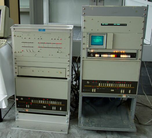
Bob Shannon's 2113 system at the 2004 VCF East show...

The following pictures were sent to me by Bob around the beginning of 2004.
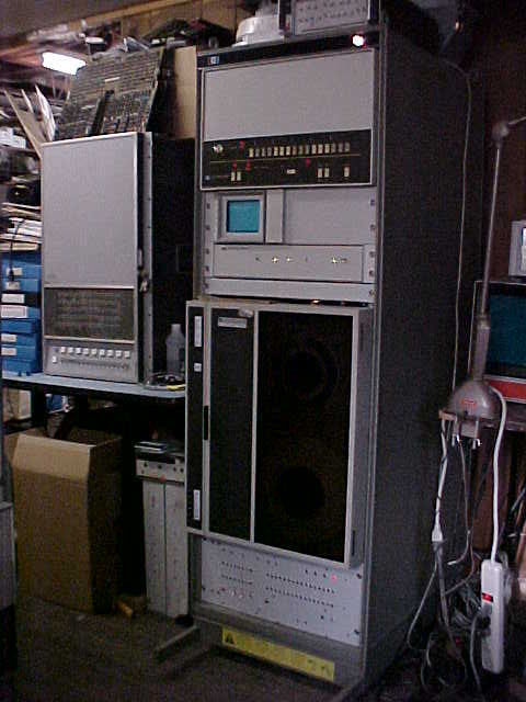
(comments by Bob Shannon)
Main system.jpg - This shows my 'main' machine with the 2113 CPU at the
top of the rack, and a HP 1335 variable persistance X/Y display just below
the CPU box. Below the HP 1335 display is a HP 1350A Graphics Translator,
the vector display generator box. Next we have a filler panel and my HP
7970E mag-tape drive. At the bottom of the rack we see the combo paper
tape reader and punch emulator (left hand side) and prototype IDE controller.
Sitting ontop of the main system rack there is a HPIB bus analyzer and a stack of mag-tape. To the left of the main system you can see a HP 2116B awaiting restoration.
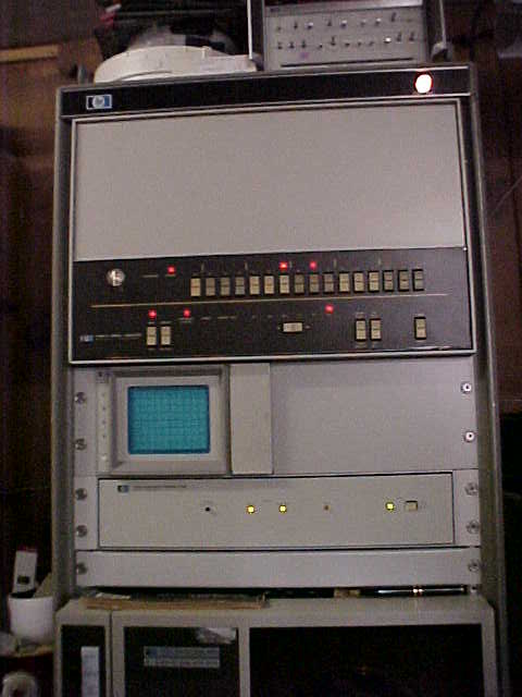
Main 2113 CPU.jpg - Here we see the main CPU (running) along with the HP 1335 display (off) and the HP 1350 display processor (also running). This is probably the best shot I have showing the LED's being lit.
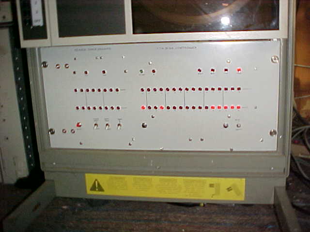
HP-IDE Disk Controller.jpg - Well, this is probably your first good look at this thing! To the left hand side you can see the tape reader data (top row) and tape punch data (bottom row) LEDs. Two LEDs on top indicate that a tape READ or tape PUNCH operation is in progress. The reader and punch emulations use a 20 Mhz 16F877 and serial I2C EEPROMs for data storage. A series of switches allow me to read from tape image 1 or 2, or to read from a host PC application (like your box). The third switch allows me to punch to tape image 2 or to a host PC application (not yet written). The red button resets the emulator for the next boot / punch operation.
On the right hand side you can see the 16-bit data output to the HP in the top row, and 16-bit data from the HP in the bottom row. The HP output data is 1100017, the last IDE command sent during a cold boot, so the CPU has recently booted from disk here. The status LEDs above the top row show things like disk busy, error, block input and block output modes, and the command state LED is currently lit.
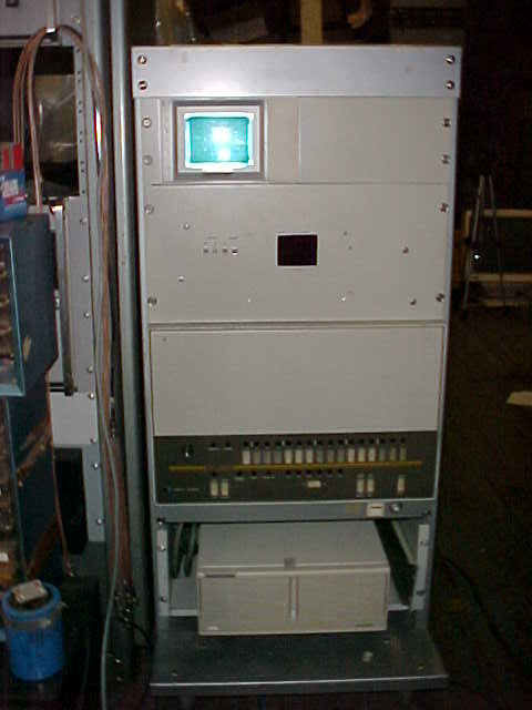
Debug System.jpg - Here's another HP-IPL/OS system I use for hardware testing and debug. At the top we see another HP 1335 display, and my original paper tape reader emulator below. This emulator uses EPROM chips and is ultra-fast (sub 2 second boot times). It holds six bootable images, and has boot from host PC and boot from a physical (Decitek) tape reader modes. Another HP 2113 CPU is below the emulator.
Just below the CPU you will see a HP 9166 CS/80 disk drive. This currently holds two 300 mb drives but has room for a third drive also. The disk drive chassis is actually a bit deeper than the CPU, so I've got it sitting on a rack-mount shelf sticking forward to it stays put on this short, roll-around rack.
This is basically the system I'm planning on bringing to VCF East, only with the IDE controller in place of the emulator it has now, and the HP 1350 box in place of the CS/80 disks.
Speaking of CS/80 disks, this system boots and runs Steve Robertson's SDOS.
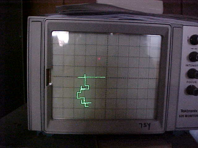
Random Vectors - This is a shot of the display generated by the HP 1350 vector box. I was just screwing around with some code to draw random lenght vectors in random directions making 90 degree turns. I've since rewritten that code for a much nicer looking display. The display tube here is a Tektronics 420, not one of the HP X/Y monitors (the Tek X/Y montitor sits next to my terminal).
I should have taken a screenshot of ROCKS on the HP 1335 display when I had the camera!
[More photos from Bob received June 2005]
I just got a slick little digital camera. I'm now able to take great shots of the vector display from the HP 1350. Here are a few new photos of several of my systems.
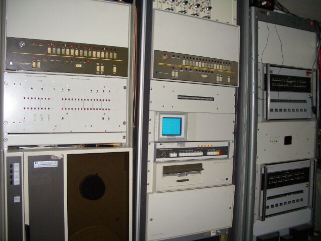
Photo 13 shows my 'main system' with the IDE disk, my 'third' system is at the center and a dual 2114 rack at the right.
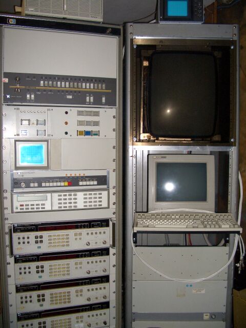
Photo 16 shows 'system two', with the 'Secure Reader / Punch Emulator and System Status panel just below the CPU. Below that is a stack of instruments all operated under IPL control for some of my 'other experiments'. Mainly what you see are ultra-accurate signal generators.
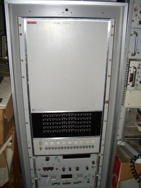
Photo 24 shows a HP 2116C with a HP 2401 DVM (with nixi tube display). Below the DVM is a 600 channel cross-bar scanner and analog data amplifier. All these instruments are controlled by special interface boards in the HP.
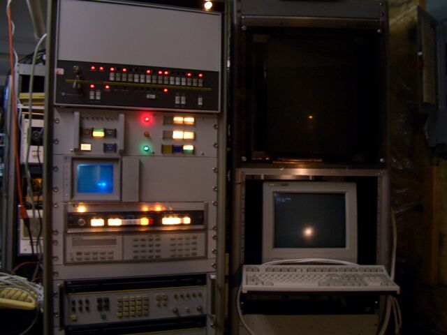
Photo 4 shows 'System two' running.

Photo 7 shows a screen shot from a HP 1350 vector translator.
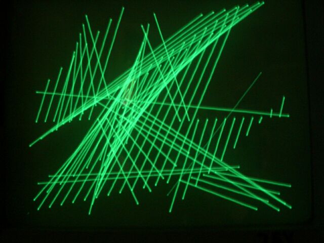
Photo 9 shows a qix-like demo program Naomi wrote.