12/28/20 - I have cable TV with a cable box, but would also like
to watch over-the-air DTV preferably without having to flip a
switch. My cable box outputs on channel 3 and fortunately there is
no channel 3 in my area, so it should be a matter of just
combining the two signals.. but that's easier said than done. In
my apartment DTV reception is already marginal so any appreciable
loss is undesirable. Then there are reflections.. ideally each
signal should see a 75 ohm load or some of the energy bounces back
to the source. A good source should absorb most of the reflection
so it's just wasted power but if it bounces back again then the
reflections combine and can cause ghosting or other bad effects.
Another potential problem when mixing RF signals is if there are
any non-linearity then new frequencies can be created causing
unpredictable effects.
An ordinary splitter can function as a combiner in a pinch but as this
page explains it leaves a lot to be desired.. not only does
it cause reflections but at best it causes a 3db signal loss plus
another db or more from the transformer. It's tempting to use
resistors to do the mixing then follow it up with a preamp but
that adds noise to the signal and the preamp can cause
non-linearity if not carefully designed, not to mention yet
another thing needing power. Then a light bulb flipped on - since
the cable box outputs a fairly strong signal and it's the antenna
signal is weak, just use resistors and weight the losses towards
the cable box.
Here's what I ended up with...
The resistor values are basically just what I had laying around,
had to parallel to get close to the values I wanted. A 22 ohm
resistor for the antenna and 56 or 68 ohm resistor for the cable
should work about the same. For such a simple circuit it has
specifications that aren't all that bad... with the resistors I
used the antenna input has an input impedance of 73.7 ohms,
almost an exact match, the cable input has an input impedance of
about 103 ohms which is a bit of a mismatch but that only reflects
about 2.5% of the signal. Output impedance is 57.6 ohms, not too
far off. Voltage loss from the antenna to the TV calculates to
about -3.7db, and from the cable input to the TV calculates to
about -7.6db. These figures don't include cable and connector
losses or parasitic inductance and capacitance.
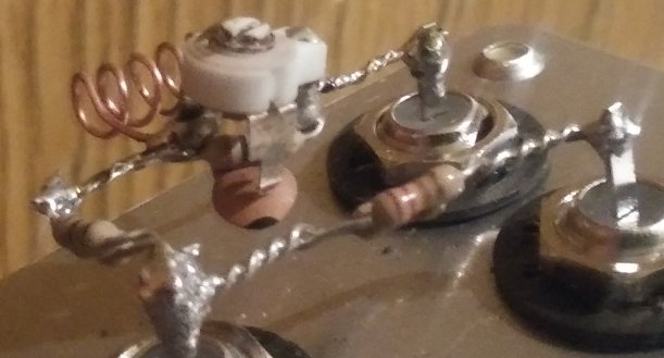
Here's a picture of my very hacked prototype, built into a scrap
300-to-75 "rabbit ears" adapter...
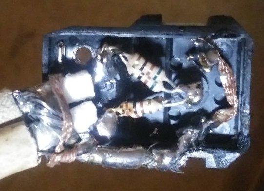
That's... just... lovely. The coax cables had aluminum shield
wires which were impossible to solder to, so wrapped them up
tightly using solderwick and coated it with solder to keep it
tight, at least until I can rebuild it in a metal box with proper
connectors.
Despite the crappy construction it seems to work ok. There's a
slight amount of RF interference on the cable signal but it's not
noticeable except on dark scenes and then only if I look for it
(it's still better than what I get using my Roku through RCA
cables). The TV side is perfect but it's digital so wouldn't
notice anything unless it was on the verse of failing. When I
first hooked it up it seemed like I lost a couple of the weaker
channels but after properly mounting the antenna to the wall I got
even more channels.
I don't think the slight amount of RF interference is due to the
lack of shielding (I can touch the connections and it doesn't
change), rather the logical source would be from the antenna
itself - any interference it picks up in the channel 3 band is
mixed with the analog cable signal, I'd be more surprised if there
wasn't at least some effect. Adding a channel 3 notch filter to
the antenna side might help.
BTW the antenna I'm using is an Antennas Direct Clearstream
Eclipse amplified - it rocks! I'm in a basement so reception is
sketchy at best, other antennas I've tried barely worked but this
thing picks up all the local channels with minimal fiddling.
1/1/21 - Take two...
Got parts from the Radio Shack at my amp shop (yeah!) and made a
better version of the combiner...
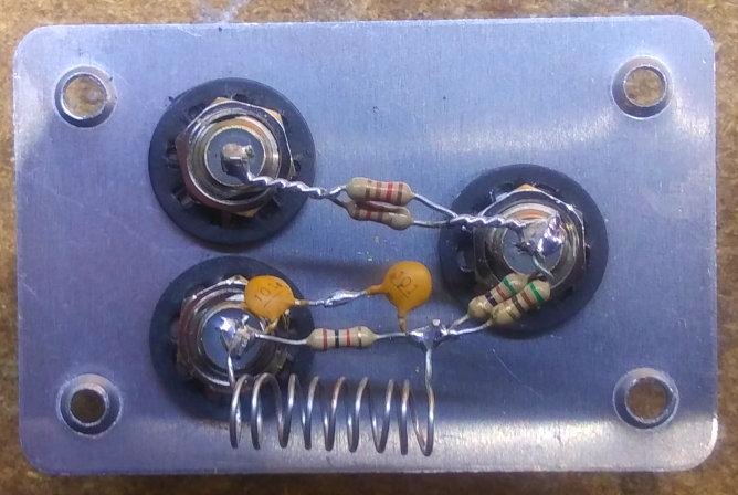
Used the same values for the resistors 25.5 ohms (2 by 51 ohm)
for the antenna side, 60 ohms (2 by 120 ohm) for the cable side,
with a channel 3 trap filter on the antenna side consisting of a
135nH (thereabouts!) inductor paralleled with 50pF (2 100pF in
series) and a 1K resistor, notch frequency is supposed to be
61.25Mhz. According to a popular coil formula - L(uH) ~=
(Nturns*Diameter)^2 / (18*Diameter + 40*Length) - 135nH should be
9 turns, outside diameter 0.25" and length 0.825" (the coil in the
picture is closer to 0.8" long) but I don't count on it being
exact.. the 1K parallel resistor drops the Q and the notch depth
so that it attenuates over a much wider range. Channels 2, 4 and 5
in my area have a relatively strong signal so a broadband notch is
fine even if it doesn't hit channel 3 exactly. Here's what LTspice
has to say about it...
Of course this assumes that the inductor is really 135nH (which
likely is not.. lucky if it is somewhere between 120nH and 150nH)
and the capacitor is really 50pF (which it likely is not, probably
10% tolerance) and ignores parasitic effects. I have no idea what
the actual response is. Compress the coil windings to raise the
inductance and lower the notch frequency, expand the windings to
increase the notch frequency. The easiest way to tune it without
equipment is to connect the cable to the antenna input then adjust
the coil for maximum signal loss.. if the notch point isn't
apparent short the output connector with an alligator jumper to
degrade the signal. Don't worry if it doesn't land exactly on the
notch point, just needs to be in the ballpark. On mine I ended up
with a coil length of just under 0.8". Adjustment would have been
a lot easier with a trimmer capacitor. If it can be adjusted with
reasonable precision then the parallel resistor can be increased
to say 10K to narrow the notch for less impact on the surrounding
channels (or I could have used a pre-made channel 3 trap in series
with the antenna but that's not as much fun...).
I didn't have to adjust it much - it worked mostly perfectly from
the start with hardly no impact on the surrounding channels
(digital being what it is.. either works perfectly or hardly at
all) but adjusted anyway to verify the coil calculations. Better
yet the slight amount of RF interference the hack version had on
the cable signal is totally gone now, the picture is perfect. I
did notice a possible reduction of sensitivity on one of the UHF
channels (hard to tell, the channel was already weak),
re-positioning the antenna fixed that but I might replace the
capacitor with a 47pF 0603 surface-mount type with wires soldered
to the ends for a more straight-through path.. high frequencies
really don't like to turn corners.
1/10/21 - Take 4 (take 3 didn't work out..). Although the version
with the 135nH/50pF filter worked OK, the notch response bugged me
- taking out more of channel 2 and channel 4 on the simulation (in
my area those channels are strong but if not would not have worked
as well). After fiddling around with the simulation and studying a
bit about tank circuits I learned that reducing the
"characteristic impedance" (the reactance of the L and C
components at resonance) helps a lot to flatten out the response
before and after the notch...
Going to 10K for the parallel resistor sharpened it up some but
that wasn't all of it, here's the response with the original coil
and cap values...
At first I tried for L~=44nH C~=150pF but that was a no-go - the
smaller the coil is the harder it is to fabricate with reasonable
accuracy. Plus thinking I'd be stabilizing things (was compressing
and expanding the coil to tune) I made the filter on perfboard and
used epoxy on the back side to lock it all in place. Couldn't even
find a null. Used the same values but air-suspended, found a
sort-of null but with this small of an inductor it's just too hard
to turn.. as soon as I let go the null went away. Put it aside (it
worked fine), then the other day at the amp shop I found a
variable trimmer capacitor - ~10pF to 100pF (and totally
unobtainium like most trimmer caps these days). Mouser has a
similar 6pF to 65pF trimmer in stock (at the moment), Vishay part
number BFC280831659. They also have 56nH inductors, part number
1026R-10J but don't know how they'd work for this.
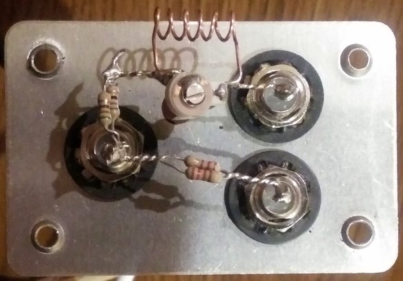
I wound my own coil - 6 turns, 0.2" outside diameter, 0.55"
length per ECALCS...
To get in the range of the prescribed 117pF I paralleled a 68pF
capacitor (for the 65pF trimmer from Mouser use a 100pF), along
with the 10K damping resistor. This time running the cable through
the antenna side I got a noticeable null, even without having to
degrade the signal by shorting the output. Definitely easier to
adjust when using a trimmer capacitor, just use something
non-metallic. Here's what it looks like now...
This will probably do. Actually for the most part this concept
works fine even without the channel 3 notch filter, just picks up
a bit more RF interference (and not that much, have to look for
it). With the filter in place it has about 3db less loss on the
cable side, about +/- a few degrees phase shift going on around
channel 3 but I see no effect from that. Probably more than
anything it was an exercise in figuring out how to use the
air-core coil winding formula but without RF test equipment all I
can really tell is that it's in the ballpark.
Terry Newton (wtn90125@yahoo.com)